


Source connections
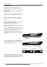
7-2 5975638 BARCOGRAPHICS 1209s 010797
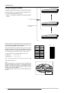
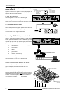
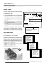
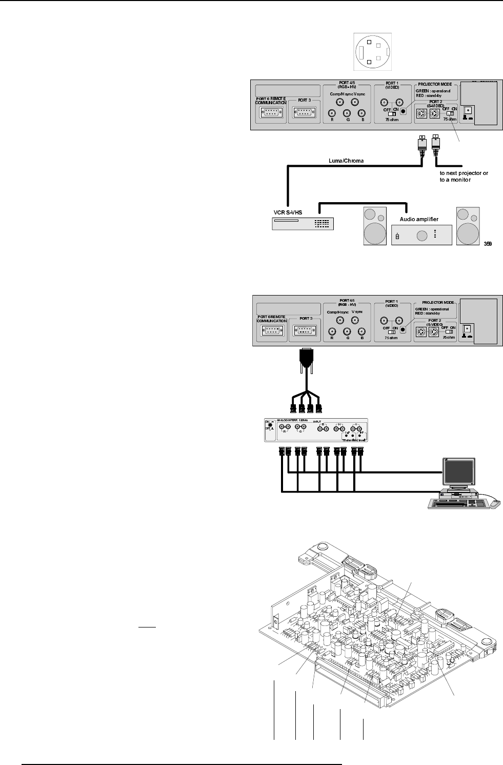
Connecting a S-Video (or Composite Video)
source to Port 2
Separate Y-luma/C-chroma signals for higher quality playback of
Super VHS signals can be connected to Port 2 . A composite video
signal can also be connected to this port.
To select the S-video input :
Press the digit button 2 on the RCU or the local keypad.
In case of using Port 2 for connecting the Composite Video, the
selection of this source have to be done inside the "Picture Tuning"
menu. Please refer to the Owner's Manual.
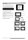
75 W Termination Switch for S-video
Terminate the S-video input of the projector using the 75 Ω switch next
to the S-video input when the projector operates alone or when the
projector is the last unit in a loop-through configuration.
The switch is set to "ON" :signal terminated.
The switch is set to "OFF":signal not terminated.
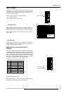
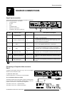
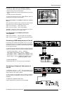
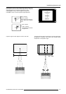
Connecting a RGB Analog source to Port 3
Connect a RGB Analog signal via an interface (e.g. RGB 120MHz
interface, part number 98 26570) to Port 3. RGB analog input with
automatic sync detection (Separate H and V sync inputs, with
composite sync input or with sync signals on green) and automatic
polarity detection.
Pin configuration of the D9 (male) connector of the Analog input :
1 not connected
2 ground RGBS
3 RED
4 GREEN
5 BLUE
6 ground RGBS
7 ground RGBS
8 Horizontal /composite sync
9 Vertical sync
To select the RGB analog Input :
Press the digit button 3 on the RCU or the local keypad.
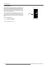
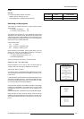
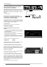
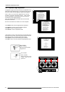
S1 Force Negative Sync
(ON=yes)
R81
Hsync
R101
Vsync
R41
(Blue)
R21
(Green)
R1
(Red)
S2 Blue in Green (ON=yes)
Line termination 75 Ω resistors
Locations of the Termination Resistors and Switches
on the RGB Input Auto Sync Tracking Module
When changing a switch position or removing a resistor, turn off the
projector and unplug the power cord from the wall outlet.
75 W Termination resistors
In case of chaining (loop-through) the projectors, the 75Ω line
termination resistors must be removed from the RGB Input Auto Sync
Tracking Module when the projector is
NOT the last unit in the chain.
In case of a stand-alone projector, do not remove the resistors.
75 Ω resistors on the module : line terminated.
75 Ω resistors removed : line not terminated.
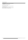
1
2
3
4
4 pin connector configurations:
For S-video:
Pin 1: earth(ground) luminance
Pin 2: earth(ground) chrominance
Pin 3: luminance signal(Y)
1Vpp ±3dB
Pin 4: chrominance signal(C)
300mVpp ±3dB
For video:
Pin 1: earth(ground) video
Pin 2: not connected
Pin 3: video signal
Pin 4: not connected
75 Ω Termination
Switch
361
RGB 120MHz interface