Source Connections
6-3
5975198 RETRODATA 808s 210397
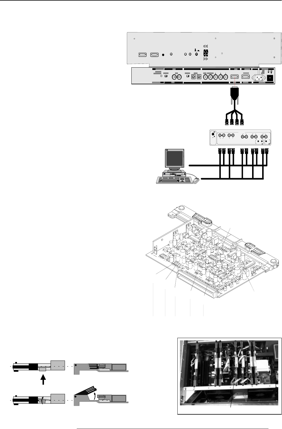
Connecting a RGB Analog source to port 3.
Connect your RGB source via an interface to Port 3.
Always use an interface when a computer and local monitor have to
be connected to the projector.
Barco interfaces which can be applied :
Universal analog interface R9826100
RGB 120 MHz analog interfaceR9826570
VGA interface 120V R9828079
230V R9828070
MAC interface 120V R9828059
230V R9828050
MAGIK interface 120V R9828129 & R9828128
230V R9828120 & R9828121
RGB analog input with automatic sync detection. (Separate H and
V sync inputs, with composite sync input or with sync signals on
green)
Pin configuration D9 connector of the Analog input.
1 not connected
2 ground RGBS
3 RED
4 GREEN
5 BLUE
6 ground RGBS
7 ground RGBS
8 Hor/comp. sync
9 Vert. sync
Analog Input Selection :
with the RCU or build in RCU, press digit button 3.
PORT 4/5
See ins tallation ins tructions before conn ecting t o the suppl y.
Voir l a notice d' installat ion avant de raccorder au réseau.
120/230 V
7/5 Amp
50/60 Hz
75 Ohm
PORT 2
75 O hm
Thi s device co mplies w ith part 15 of
the FCC ru les. Operation is subject to
following two conditions (1). This
device may not c ause har mful inter-
feren ce, an d (2) t his device must
accep t any int erfere nce rece ived
inclu ding in terfer ence th at may c ause
undesired operation"
RS232 IN
RS232 OUT IR
REMOTE
RS232 INRS232 OUT
IR
REMOTE
EXTERNAL
INTERNA L
L
R
R
L
R
L
LR
PORT 4/5
PORT 2
INP
INP
R
G
BH
V
INPUT
ANALOG INTERF. 120MHz
ON
OFF
inver.
75 ohm term.
Locations of the Termination Resistors and Switches
When changing a switch position or removing a resistor, turn off the
projector and unplug the power cord from the wall outlet.
75 ΩΩ Termination resistors
In case of chaining (loop-through) the projectors, the 75Ω line
termination resistors must be removed from the RGB Input Auto Sync
Tracking Module when the projector is the last unit in the chain.
In case of a stand-alone projector, do not remove the resistors.
75 Ω resistors on the module : line terminated.
75 Ω resistors removed : line not terminated.
S1 Force Negative Sync
(ON=yes)
R81
Hsync
R101
Vsync
R41
(Blue)
R21
(Green)
R1
(Red)
S2 Blue in Green (ON=yes)
Line termination 75 Ω resistors
RGB Input Auto Sync Tracking Module
Procedure to remove the line termination resistors :
➊ Turn off the projector and unplug the projector power cord.
➋ Put the projector in service position 2 (see p.5-2).
➌ Take out the RGB Input Auto Sync Tracking Module from the main
frame.
➍ Unsolder and remove the resistors.
To take out the RGB Input Auto Sync Tracking Module :
➊ press the module lock and lift up the module handle;
Top view
Top view
Side view
Side view
➋ repeat this action on both sides of the module and extract the
module out of the main frame.
Order number D9-
BNC cable : R9827840


