


How to Use Data Communications
19
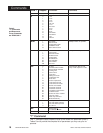
WATLOW Series 945
Commands
Data.1 Data.2
Low Limit High Limit Code Function
AXHI Process RL value RH value Alarm High X value
±555/Deviation ±999
A
XLO Process RL value RH value Alarm Low X value
±555/Deviation ±999
ALM 0 No alarms occurring Writing a 0 will clear all
1 A1H occurring alarms if the alarm
2 A1L occurring condition no longer
4 A2H occurring exists.
8 A2L occurring
AL1 0 2 0 Alarm 1 = deviation
1 Alarm 1 = process
2 No Alarm 1
AL2 0 2 0 Alarm 2 = deviation
1 Alarm 2 = process
2 No Alarm 2
ATMN 1 1 1 Auto/Manual toggle must
be sent twice within 5 sec.
AUT 0 3 0 No auto-tuning
1 Slow response tuning
2 Medium response tuning
3 Fast response tuning
CAL* -180°F 180°F Calibration offset
-100°C 100°C
-180 Units 180 Units
CF 0 1 0 Display °C
1 Display °F
CLUP Yes No SPC control limits update
CT
X 1 60 Output X cycle time
DAY 1 31 Day of the month/data log
DB 099°F Dead band
055°C
0 Units 99 Units
DEC 0 2 0 No decimal point
1 0.0
2 0.00
DE
X 0.00 9.99 Output X derivative
DFL 0 1 0 US prompts
1 SI prompts
HOUR 0 23 Hour for data logging
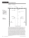
HYS
X 1°F99°F Output X switching hys.
1°C55°C
1 Unit 99 Units
INDC 1 1 1 UP/DOWN key action
INT 0.0 60.0 Time interval in minutes
for logging
0.0 = logging OFF
IT
X 0.00 9.99 Output X integral
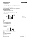
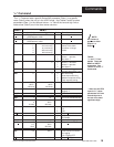
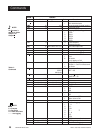
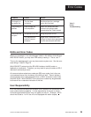
"=" Command
"The "=" Command sets a specific Series 945 parameter (Data.1) to a specific
value (Data.2) when the unit is in the HOLD mode. Use Tables 5 and 6 to select
parameters (Data.1) in the lefthand column. In Table 6 the low and high limit or
code values (Data.2) are in the three center columns.
NOTE:
An X means it
applies to either
Output 1 or
Output 2.
* When the 945 RTD
input is 0.1
°, these
parameters will have
a decimal point to
the left of the least
significant digit.
Table 6 -
"=" and "?" Com-
mands. These are
READ or WRITE
commands. See
Table 4 for more "?"
Commands.