


How to Use Data Communications
21
WATLOW Series 945
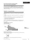
Data Logging
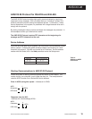
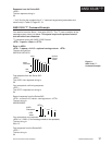
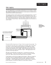
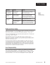
Figure 10 -
Data Logging
Interface Wiring
Example.
Data Logging
The data logging feature is a convenient replacement for chart recorders. Informa-
tion is sent directly from the Series 945 to a serial printer, or to a computer disk file.
No computer is needed, although the 945 can be connected to a computer with a
serial port and terminal emulation software.
Data logging provides a handy reference to review process performance. The time
intervals between each entry and data printed are user selectable, with the time
display resetting every 24 hours. If there is a power interruption, the time is reset to
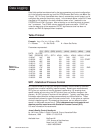
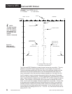
0.0. There are several options for the printer output. Choose from table, chart or
SPC (Statistical Process Control). See the following pages for more information on
printer outputs.
Connect the 945 to the printer as in Figure 10; this is a typical wiring example. The
connections on the printer may vary depending on the model, refer to the printer's
user manual. Enter the Setup menu by pressing the UP/DOWN keys simulta-
neously for three seconds. Mode through the parameters until you reach bAUd
and follow the parameter listing on Page 8. Select the appropriate data for each
prompt and enter your values in the table on Page 9. Data logging begins once
you return to the control set point.
After each line the 945 emits a carriage return. Your printer can be set up to
handle line feeds. The printer must supply a line feed (LF) following a carriage
return (CR). Refer to your printer user's manual for more information.
A data header is printed once the logging function begins. When you change the
time interval (Int) or any selected data (tag), or power is cycled, the header is
printed again. The header always remains the same, regardless of the control
configuration. The time display wraps around to 0.0 every 24 hours. If there is a
power interruption, the control will restart at 0.0 when power is restored.
Series 945 #
1
20
21
23
Signal Common
Com
T
Jumper to Signal Common
2
3
4
5
9
8
7
6
10
12
13
4
15
16
17
18
19
2 0
21
22
23
24
25
R
RLSD (Received Line Signal Detector)
DSR (Data Set Ready)
RTS (Request To Send)
CTS (Clear To Send)
22
Jumper DTR, DSR, and RLSD together.
Also, jumper RTS and CTS together.
Refer to your printer's user manual.
R
DTR (Data Terminal Ready)
T
11
Host Computer
(rear view)
Printer
DB-25 female connector
(located on back of printer
viewed from wire side)