


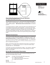

How to Use Data Communications
4
WATLOW Series 945
19
20
21
22
23
T +
T -
R +
R -
Signal Common
(Optional)
Series 945 #
1
Series 945 #1
0
Twisted Pair Wire
1
2
3
4
5
9
8
7
6
19
20
21
22
23
T +
T -
R +
R -
Signal Common
(Optional)
Twisted Pair Wire
T +
T -
R +
R -
Com
Host Computer
(rear view)
DB-9 female
connector
(viewed from wire side)
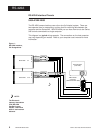
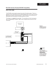
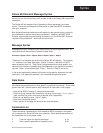
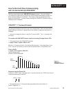
RS-422A
RS-422A Interface Pinouts
945A-XXXX-B000
The RS-422A communications uses a four wire (full duplex) system. There are
two separate lines for transmitting, and two lines for receiving data between the
computer and the Series 945. With RS-422A you can have from one to ten Series
945 controls connected to a single computer.
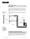
This diagram is a typical wiring example. The connections on the host computer
may vary depending on models. Refer to your computer user's manual for more
information.
Figure 1 -
RS-422A Interface,
Pin Designations.
NOTE:
The Electronic
Industry Association
(EIA) RS-422A
standard recom-
mends a maximum
4000 ft. total network
distance.