


How to Use Data Communications
6
WATLOW Series 945
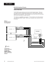
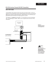
EIA-485 Interface Pinouts
945A-XXXX-D000
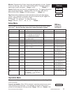
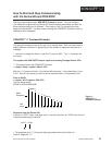
The EIA-485 communications uses a two wire (half duplex) system. There are only
two lines, both lines used for transmitting and receiving. Only one device, the
computer or the control, can be speaking at a time. There is a 1 millisecond delay
requried for the Series 945 to go between transmission and receipt of data. With
EIA-485 you can have from one to thirty-two Series 945 controls connected to a
computer.
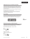
This diagram is a typical wiring example. The connections on the host computer
may vary depending on models. Refer to your computer user's manual for more
information.
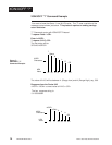
T+/R+
T-/R-
EIA-485
Figure 3 -
EIA-485 Interface, Pin
Designations.
19
20
23
T+/R+
T-/R-
Signal Common
(Optional)
Series 945 #
1
Series 945 #31
Twisted Pair Wire
1
2
3
4
5
9
8
7
6
19
20
23
Signal Common
(Optional)
Twisted Pair Wire
T+/R+
T-/R-
Com
Host Computer
(rear view)
T+/R+
T-/R-
DB-9 female
connector
(viewed from wire side)
NOTE:
The Electronic
Industry Association
EIA-485 standard
recommends a
maximum 4000 ft.
total network dis-
tance.
#32
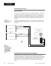
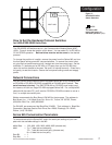
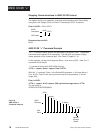
Connecting the Control and the Computer
Remove power from both the Series 945 and your computer or printer before
connecting them together. This prevents noise or static interference from entering
the data communication lines. Assemble a cable and the appropriate wiring at your
computer or printer. Refer to the wiring on Page 4 through 6. As soon as you
connect the data communications line(s), you're ready to apply power to your
system.