


52
SERVSWITCH™ WIZARD EXTENDER
The first section of the report indicates the length differences between the twisted
pairs that are carrying the red, green, and blue color signals. One of the colors will
have a reported length difference of “+0.0M”; this is the color carried by the shortest
twisted pair. The other reported differences are how much longer the other pairs
are than the shortest one.
TECHNICAL NOTE
Each meter of the length differences between the pairs that the Extender
reports is equivalent to 5 nanoseconds of delay. For comparison, you
can get a rough estimate of your system’s on-screen “pixel time” by
multiplying the horizontal pixels by the vertical pixels by the refresh rate
and then dividing 1 by the result. If the delay time is greater than the
pixel time, color split will be noticeable.
For example, if the maximum reported difference is 1.5 meters, the
delay between color signals will be 1.5 x 5 ns = 7.5 ns. If the screen
resolution being used is 1024 x 768 x 75 Hz, the pixel time is roughly
1 / (1024 x 768 x 75) = 16.9 ns. Consequently, the color split will be less
than half a pixel time and so is unlikely to be noticeable.
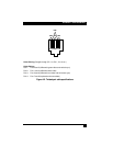
The second section of the report indicates which of the Skew Compensator’s
top-panel switches should be set to ON to compensate for the twisted-pair length
differences indicated by the report. All other switches should be OFF. You will see
that each of these switches is constructed using 4 individual sliders. To set a switch
to ON, all four sliders must be moved to the ON position. To set a switch to OFF,
all four sliders must be moved to the OFF position. The example skew report on
the previous page indicates that switches A3 and B4 should be ON and all the
other switches should be OFF.
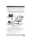
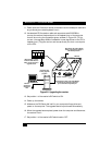
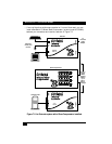
To compensate for the skew, set the Skew Compensator’s switches as indicated in
the report and use a second cable to insert it into the twisted-pair cable run
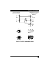
between the transmitter and receiver, as shown in Figure 7-2. If this is a lower-
quality patch cable, it should be as short as possible. It doesn’t matter which cable
you plug into which of the Compensator’s two RJ-45 jacks; the Compensator is fully
bidirectional.
NOTE
Because the cabling between the CPU and the transmitter can itself
introduce some signal skew, sometimes setting the Skew Compensator
manually, by trial and error, produces better results than relying on the
skew report. For any given wire pair (color), switches 1 and 2 each
introduce a 10-nanosecond delay, switch 3 introduces a 5-nanosecond
delay, and switch 4 introduces a 2.5-nanosecond delay. For more
information, refer to the Skew Compensator’s manual.