


Product Overview
14 ETEP Installation Guide
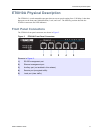
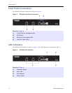
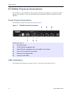
Front Panel Connectors
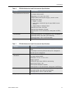
The ET0100A front panel connectors are shown in Figure 5.
Figure 5 ET0100A Front Panel Connectors
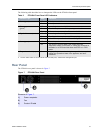
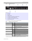
LED Indicators
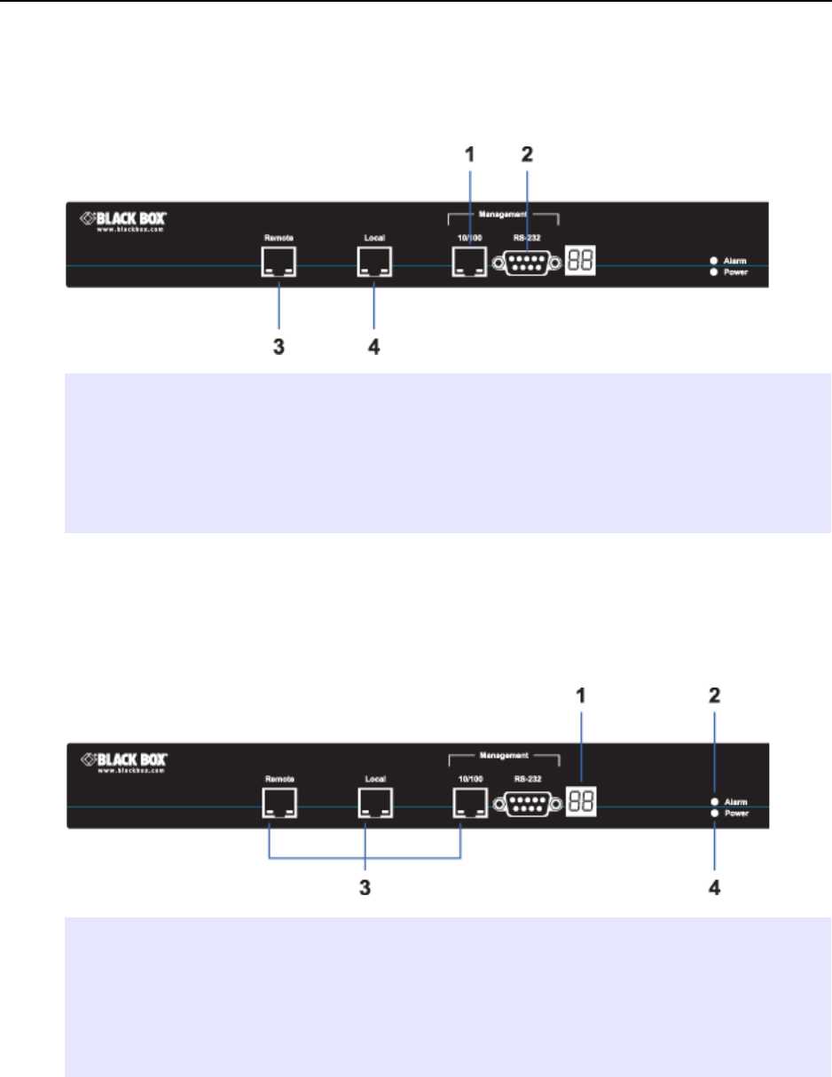
The ET0100A LED indictors are shown in Figure 6. The LED indications are described in Table 2.
Figure 6 ET0100A LED Indicators
Elements of Figure 5:
1) 10/100 Ethernet management port
2) RS-232 port
3) Remote port (encrypted traffic)
4) Local port (clear traffic)
Elements of Figure 6:
1) Diagnostic display
2) Alarm LED
3) Link indicators
4) Power indictor