


Installation
32 ETEP Installation Guide
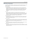
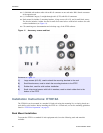
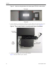
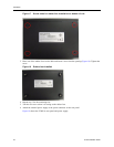
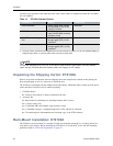
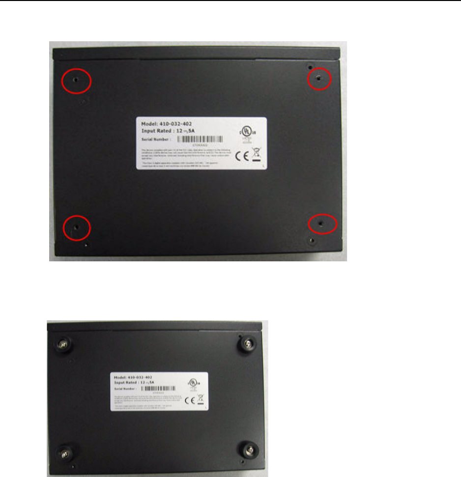
Figure 17 Screw holes for rubber feet installation on bottom of unit
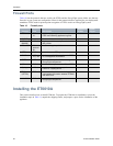
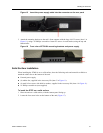
3 Place one of the rubber feet over the hole and insert a screw into the opening (Figure 18). Tighten the
screw.
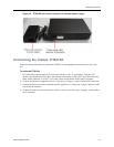
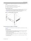
Figure 18 Rubber feet installed
4 Repeat step 3 for the remaining feet.
5 Turn the unit over so that it is resting on the rubber feet.
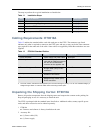
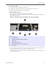
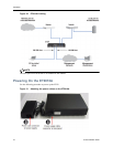
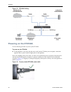
6 Attach the external power supply to the power connector on the rear panel.
Figure 19 shows the ET0010A rear panel and power supply.