


Installation
28 ETEP Installation Guide
● (1) Shielded null modem cable with an RJ-45 connector at one end and a DB-9 female connector
at the opposite end.
● (1) Unshielded Category 5 straight through cable (UTP) with RJ-45 connectors
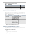
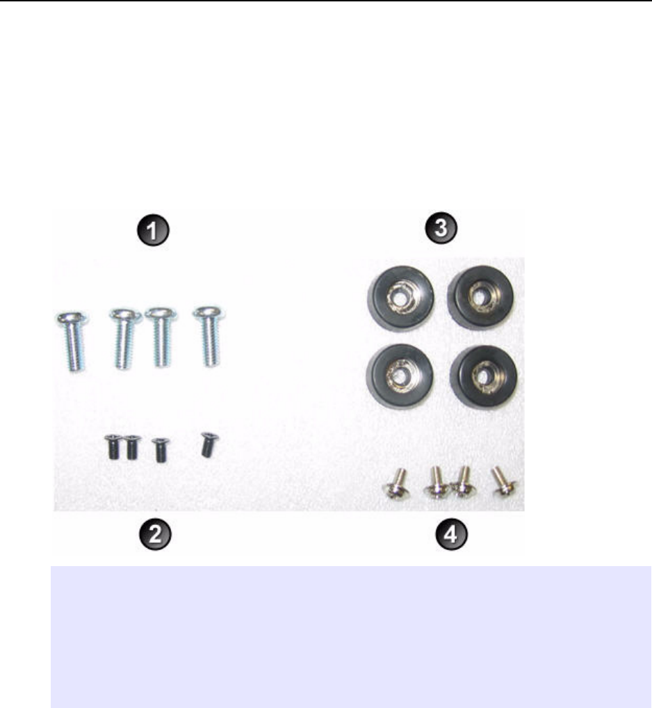
● Rack mount kit includes 2 mounting brackets, 4 large screws (#10-32), and 4 small black screws.
The kit also includes 4 rubber feet and 4 small silver-toned screws with built-in washers for solid
surface installations (see Figure 11).
● CD containing user documentation and a backup copy of the ETEP software
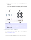
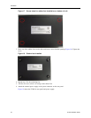
Figure 11 Accessory screws and feet
Installation Instructions: ET0010A
The ET0010A can be mounted in a standard 19-inch rack using the mounting kit, or simply placed on a
rack shelf or solid surface. Before installing the ETEP in a 19-inch rack, review the mounting guidelines
listed in “ETEP Site Preparation” on page 25.
Rack Mount Installation
To mount the ETEP in a standard 19-inch equipment rack, have the following tools and materials
available:
Elements of Figure 11:
1) Large screws (#10-32), used to attach the mounting brackets to the rack
2) Small black screws, used to attach the mounting brackets to the ETEP
3) Rubber feet, used for solid surface installation
4) Small silver-toned screws with built in washers, used to attach rubber feet to the
bottom of the ETEP