


724-746-5500 | blackbox.com
Page 15
Configuration
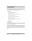
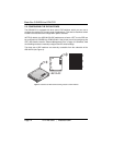
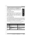
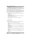
The three sets of DIP switches on the underside of the LB510A-R2
are referred to as S1, S3 and S4. For basic configuration, use DIP
switch S1. For testing the LB510A-R2, use DIP switch S3. To con-
figure the ra
te, use DIP switch S4. This figure shows the DIP
switch orientation, with respect to ON and OFF positions, is consis-
tent for all switches.
2.4 SYSTEM RESET MODE
To enter system reset mode, turn the S1-1 DIP switch to the ON
position and power cycle the unit. For information on how to
upgrade the software, refer to section 6 “Software Upgrade” on
page 33. For more information on applying factory default configu-
ration to the LB510A-R2, refer to section 7 “Reset configuration to
fa
ctory defaults” on page 34.
2.5 DIP SWITCH SETTINGS
You can configure the LB510A-R2 by setting the DIP switches to the desired positions
before you power up the device. If the DIP switches are set to anything other than all
OFF or all ON, the LB510A-R2 will operate in DIP switch configuration mode. Once the
device is powered up and operating in DIP switch configuration mode, you cannot
change configuration by any method until you power it down again.
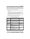
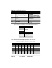
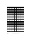
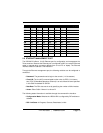
The following tables provide an overview of the LB510A-R2 DIP switch functions.
Table 2:
LB510A-R2 S1 DIP-Switch functions (configuration)
Position Function Settings
S1-1 Software Reset
Software Reset
S1-2
Reserved
Reserved
S1-3
S1-4
No Management Port
(All Ethernet ports are used for
data only)
ON - All ports used for data only
OFF - Any port can be used for
man
agement
(if S1-5 is also OFF)
OFF
ON
1 2 3 4 5 6 7 8
ON