


724-746-5500 | blackbox.com
Page 24
Black Box G.SHDSL.bis EFM CPE
3. INSTALLATION
Once the LB510A-R2 is properly configured, it is ready to connect to the DSL interface
and to the power source. This section explains how to make these connections.
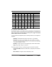
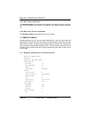
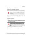
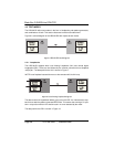
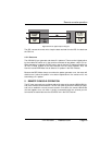
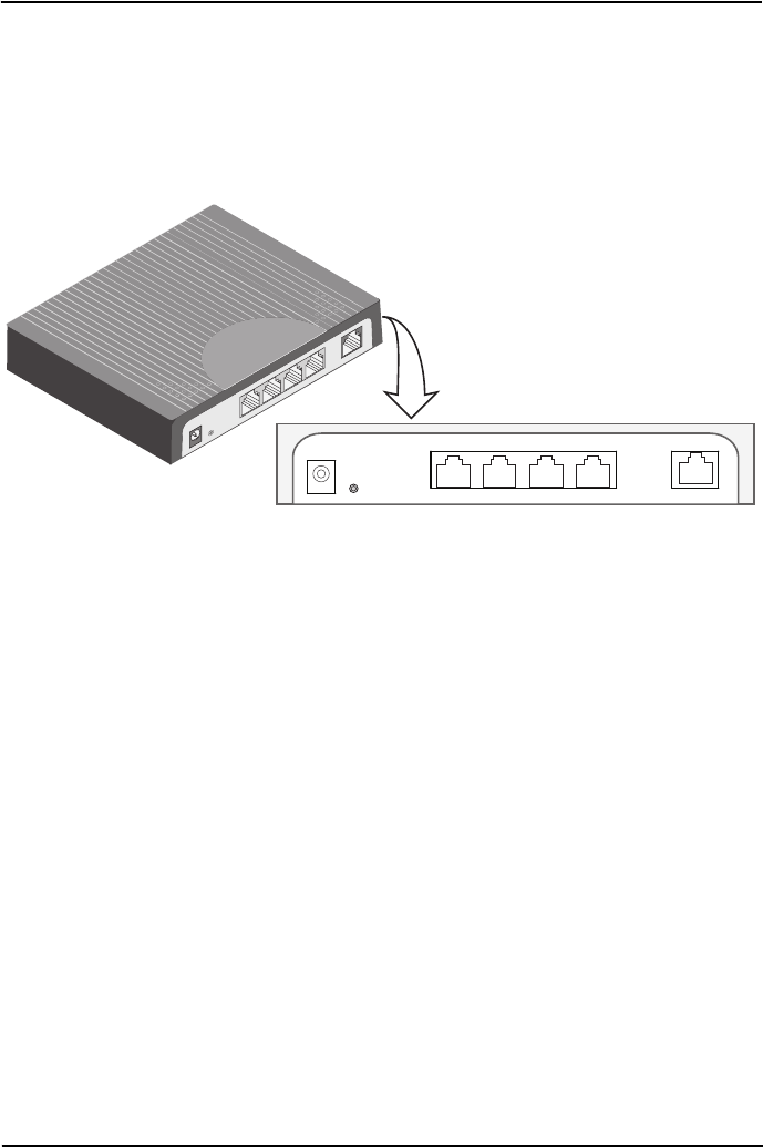
Figure 4.
LB510A-R2 rear panel
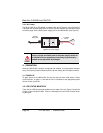
3.1 CONNECTING THE DSL INTERFACE
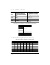
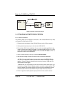
The LB510A-R2 supports communication between two DTE devices as follows.
Using 24 AWG (0.5 mm) wire up to:
• 18,000 feet (5.48 km) at 192 kbps
• 11,000 feet (3.5 km) at 5696 kbps
Two things are essential:
1. These units work in pairs. Both units at the end of the twisted pair DSL span must
b
e set for the same DTE rate—one unit set as CO, the other as CP.
2. To function properly, the LB510A-R2 needs one twisted pair of metallic wire. This
twisted pair must be unconditioned, dry, metallic wire, between 19 (0.9mm) and 26
AWG (0.4mm) (the higher number gauges will limit distance). Standard dial-up
telephone circuits, or leased circuits that run through signal equalization equip-
ment, or standard, flat modular telephone type cable, are not acceptable.
Reset
LB510A-R2
(DSL, Multi-Port Etherne
t)
Eth 0 DSL
Reset
Eth3
Eth0
Eth1
Eth2
DSL
Eth 1 Eth 2 Eth 3