


8.0 Maintenance and Adjustments
Your ticket printer is solidly constructed and has been designed for high volume use. It
requires minimal care to provide maximum service.
This section provides an overview of printer maintenance, including part alignments,
adjustment and replacement.
For discussion purposes, the printer consists of three major modules or assemblies:
• Paper guide and print head assembly
• Cutter assembly
• Logic board assembly
As a safety precaution, all service to the printer should be done with power off
and the AC cord unplugged from the printer.
8.1 Paper Guide and Print Head Assembly
The principal function of this assembly is to guide the flight strip stock to the thermal
print head where thermal printing takes place. Additionally, this assembly houses the
drive platen, optical detector and ticket load switch. If necessary, the total assembly
can be removed from the unit. However, all replacements and adjustments of the com-
ponents of this assembly can be done without removing the total assembly. The most
common adjustments and replacements regarding this assembly follows:
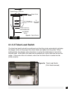
8.1.5 Optical Device (see figure 8)
There is one opto device mounted on an aluminum bracket beneath the paper guide.
The opto controls ticket cut position. Removal or adjustment of the opto should be
done without removing the bracket from the paper guide.
The opto position is factory set and adjustment should not be necessary
.
Caution: Before making any opto adjustments make sure your flight strip stock
was manufactured to proper specifications. The printer should cut the ticket just
behind the perforation. The ticket should never be cut in front of the perforation.
The position of the cut can be controlled by changing the cut count setting in the
OPERATOR MENU (see Section 5.0 - Standard Configuration).
Once a year the optos eyes should be blown off with air. This interval will vary depend-
ing upon the environment and the quality of the ticket stock.
21