


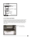

8.1.6 THERMAL PRINT HEAD
The print head should be cleaned periodically to prevent debris from building up on the
print element. The required cleaning interval varies greatly depending on the quality of
the ticket stock and the amount of dust entering the print area. Excessive dirt build up
on the print head will result in reduced quality. Continuing to run the print head in a
dirty condition will reduce its life expectancy as it is unable to diffuse its heat properly.
There are two pressure adjustment set screws (10-32 x
1
⁄
8
) located in the spring plate
above the print head. (See Figure 9a) Athough these set screws are factory set, the
pressure can be adjusted for a variance in paper thickness or to fine tune after a print
head has been replaced.
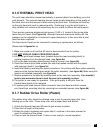
The thermal print head can be removed for cleaning or replacement, as follows:
(Please refer to figures 9a - c)
1. Make sure power is off and the AC cord is disconnected from the printer.
2. DO NO
T UNPLUG CABLE FROM PRINT HEAD.
3. Lift up the print head release lever (located above the head mounting block) to
remove pressure from the thermal head. (see figure 9a)
4. Lift up the head mounting block/thermal head to remove. (see figure 9b)
5. Clean the thermal print head surface (the side that makes contact with the paper)
with isopropyl alcohol. (see figure 9c)
8. The printer in now ready for operation. If the print quality is still poor then the
thermal head needs to be replaced.
9. To replace print head remove ribbon connector from print head and then remove
print head from mounting block by removing two unmarked screws. (see
figure 9b)
8.1.7 Rubber Drive Roller (Platen)
The rubber drive roller should be cleaned once a year to prevent paper dust from
building up on the roller. Clean drive roller with a paper towel and alcohol.
1. Unlock the thermal head and tilt back to gain access to platen.
2. Clean the full length of the platen.
3. Rotate the platen clockwise and repeat step 2, continue in the same manner for
one full revolution of the platen.
4. Close or lock the thermal head. Printer in now ready for normal operation.
23
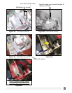
6. Install the head by reversing the above procedures. For printers with Boca cutter assembly
make sure the thermal head goes under the cutter assembly. (see figure 9d) Make sure print
head is not installed improperly (see figure 9e)
7. Restore pressure to the head by pushing down on the cam lock assembly. You shouldn’t
have to use excessive force to lock the cam lock assembly in place.