


Brocade DCX 8510-4 Backbone Hardware Reference Manual 93
53-1002177-05
Inter-chassis link (QSFP) cable removal and replacement
5
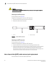
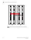
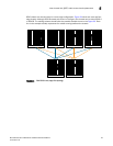
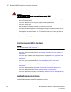
8510 chassis can be connected in a core/edge configuration. Figure 34 shows two core and four
edge chassis. Although 8510-8 chassis are shown in the figure, the chassis can be either 8510-4
or 8510-8. The cabling scheme should follow the parallel example shown in the Figure 33. Each
line in the example actually represents four cables running between the chassis.
FIGURE 34 DCX 8510 core/edge ICL topology