


Brocade DCX 8510-4 Backbone Hardware Reference Manual 21
53-1002177-05
Cable management
2
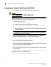
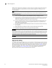
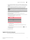
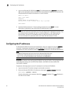
FIGURE 4 Cable design for the mSFP patch cables for the FC8-64 high density port blade
Note that the duplex clip on the mSFP end of the cable is black for easier recognition. See the
appendix for a listing of the qualified mSFP optical cables for the FC8-64 port blade.
If ISL Trunking is in use, group the cables by trunking group. The ports are color-coded to indicate
which ports can be used in the same ISL Trunking group: eight ports marked with solid black ovals
alternate with eight ports marked with oval outlines.
Refer to Table 22 in Appendix A, “Specifications” for a listing of supported cable speeds and
distances.
Installing inter-chassis link (QSFP) cables (optional)
Refer to “Inter-chassis link (QSFP) cable removal and replacement” for the procedure to install the
QSFP cables
1 mSFP connector 2 1.6 mm cable
3 Duplex clip (black) 4 SFP connector
2 3
4
1