


106 Brocade DCX 8510-4 Backbone Hardware Reference Manual
53-1002177-05
Brocade DCX 8510-4 chassis removal and replacement
5
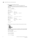
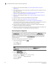
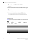
FID 1 | 1 | 1 | 1 | 1 | 128 | 128 | 128 | 128 | 128 |
<output truncated>
switch:admin>
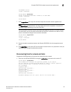
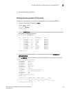
2. Determine any differences between the information in the SANafter.txt file and the information
in the SANbefor.txt file created earlier. In particular, look for differences in the following:
• Device types
• Number of devices
• ISL and port states
• Number of switches in the fabric
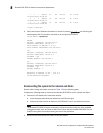
3. Resolve any issues or unintentional changes to the Brocade DCX 8510-4 or fabric:
• If there are any mechanical problems, try reseating the associated component.
• If the configuration information is not correct for the Brocade DCX 8510-4, modify as
required.
• If other issues exist, contact your support provider.
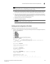
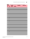
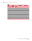
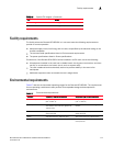
Cable routing table
Table 12 is a 64-port template for a cable routing table. Make copies of the table to cover the total
number of ports in the Brocade DCX 8510-4.
TABLE 12 Cable routing table for Brocade DCX 8510-4 (64 ports shown)
Slot/port Cable labels Connected device Slot/port of device
Slot Port Switch end Device end
0
1
2
3
4
5
6
7
8
9
10
11
12
13
14