


116 Brocade DCX 8510-4 Backbone Hardware Reference Manual
53-1002177-05
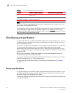
Power cords
A
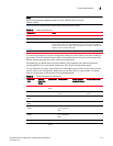
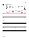
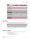
Power supply redundancy is key to your installation, so any demand must be met with twice the
capacity. See Table 20 for power supply requirements for specific demand ranges.
In addition to these tables, you can consult the power tables in the latest update of the Fabric OS
Release Notes.
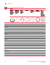
Power cords
The types of power cords provided with the Brocade DCX 8510-4 are specific to the country where it
is installed. For each of the types of power cords in Table 21, the end that connects to the Brocade
DCX 8510-4 has an IEC 60320/C19 cable connector. The AC power receptacles on each power
supply are equipped with IEC 60320/C20 power connectors.
In order to connect to a power strip already installed in a cabinet, the C20, 20A-250V, 12 AWG
power cord is required.
To order a power cord, contact your Brocade DCX 8510-4 supplier.
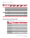
FX8-24 250 Extension
blade
12 8 Gbps SFP+
10 1 Gbps Ethernet
2 10 Gbps Ethernet
up to 4 48 8 Gbps
40 1 Gbps Ethernet
8 10 Gbps Ethernet
Fan unit 90 NA NA 2 fans per chassis NA
TABLE 20 Power supply requirements
Demand power supplies @ 110
VAC (nominal)
power supplies @ 220
VAC (nominal)
up to 1000W 2 2
1000W-2000W NA - cannot achieve
redundancy
2
greater than 2000W NA - cannot achieve
redundancy
NA - cannot achieve
redundancy
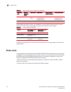
TABLE 19 Power demands per component (Continued)
Blade or fan
units
Maximum
Power Draw
(Watts)
Type of Blade Ports per blade Number of blades
permitted in chassis
Total ports per chassis