


Brocade DCX 8510-4 Backbone Hardware Reference Manual 139
53-1002177-05
Appendix
D
Port Numbering Template
Print or copy the following templates in this appendix and use them to document the port
numbering pattern for the Brocade DCX 8510-4. These templates show the following blades:
• FC16-4 core blade (Figure 36)
• FC8-64 high density port blade (Figure 37)
• FC8-32E high density port blade (Figure 38)
• FC8-48E high density port blade (Figure 39)
• FC16-32 high density port blade (Figure 40)
• FC16-48 high density port blade (Figure 41)
• FS8-18 encryption blade (Figure 42)
• FX8-24 extension blade (Figure 43)
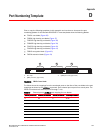
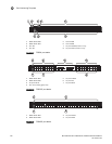
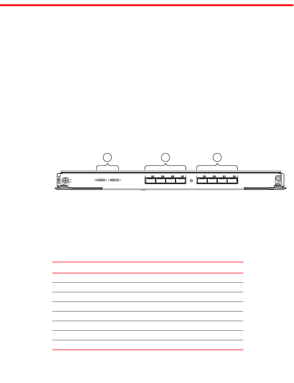
FIGURE 36 CR16-4 core blade
The follow shows the mappings from the numbered ports on the face of the core blade to the port
mappings as shown by the slotShow command. Each external port maps to four actual ports. The
CR16-4 core blade has external ports 0 through 7 only.
1 Port map 3 QSFP ports 0-3 (right to left)
2 QSFP ports 4-7 (right to left)
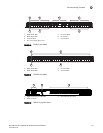
TABLE 27 External port to slotShow port mapping for core blades
External port number slotShow port numbers External port number slotShow port numbers
0 0-3 8 32-35
1 4-7 9 36-39
2 8-11 10 40-43
3 12-15 11 44-47
4 16-19 12 48-51
5 20-23 13 52-55
6 24-27 14 56-59
7 28-31 15 60-63
2
1
3