


54 Brocade DCX 8510-4 Backbone Hardware Reference Manual
53-1002177-05
Determining the status of a blower assembly
4
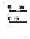
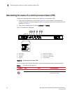
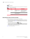
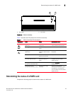
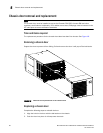
FIGURE 15 Power supply
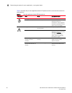
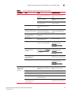
Table 6 describes the power supply LED patterns and the recommended actions for those patterns.
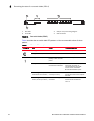
Determining the status of a blower assembly
Complete the following steps to determine the status of a blower assembly.
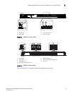
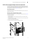
1. Check the LED indicators on the blower assembly (see the following figure). The LED patterns
may temporarily change during POST and other diagnostic tests; for information about how to
interpret the LED patterns, refer to Table 7. The Brocade DCX 8510-4 has two blowers. Be sure
to check each module.
2. Check the blower assembly status using the fanShow command.
The status for each blower assembly displays OK, Absent, or Faulty. The RPM of each fan in the
assembly is also provided. If a blower assembly displays absent or faulty, contact the Brocade
DCX 8510-4 supplier to order replacement parts. Both physically absent or faulty could also be
the result of the power supply not being properly seated.
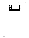
Figure 16 shows the blower assembly.
1Power LED
TABLE 6 Power supply LED descriptions
LED purpose Color Status Recommended action
Power No light
(LED is off)
Power supply does not have
incoming power and is not
providing power to the Brocade
DCX 8510-4.
Ensure that the power supply is
firmly seated, the Brocade DCX
8510-4 has incoming power, both
power cables are connected, and
AC power switches are on.
Steady green Power supply has incoming
power and is providing power to
the Brocade DCX 8510-4.
No action required.
Flashing green Power supply is about to fail. Replace the power supply.