CHAPTER 4 DISASSEMBLY AND RE-ASSEMBLY
4-10
3.4 Network Board (for HL-1270N only)
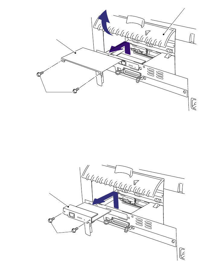
(1) Open the rear cover.
(2) Remove the two M3x8 Taptite screws to remove the access cover.
Fig. 4-15
(3) Remove the two M3x6 Taptite screws securing the network board.
(4) Disconnect the connector connected with the main PCB and remove the network board.
Fig. 4-16
Network board
Rear cover
Access cover
Taptite, bind M3x8
Taptite, cup M3x6


