


ii
WARRANTY INFORMATION ..........................................................................................II
C
HAPTER 1 – BARCODE PRINTER .............................................................................. 1
1-1 Introduction.......................................................................................................................... 1
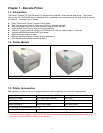
1-2 Printer Models ..................................................................................................................... 1
1-3 Printer Accessories.............................................................................................................. 1
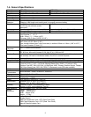
1-4 General Specifications......................................................................................................... 2
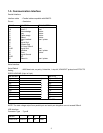
1-5 Communication Interface.....................................................................................................3
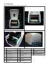
1-6 Printer Parts......................................................................................................................... 4
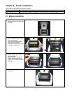
CHAPTER 2 – PRINTER INSTALLATION........................................................................ 5
2-1 Ribbon Installation............................................................................................................... 5
2-2 Label Installation.................................................................................................................. 6
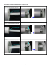
2-3 Label Roll Core Installation Instruction................................................................................ 7
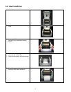
2-4 Card / Hang tags Installation ...............................................................................................8
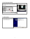
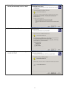
2-5 USB Installation................................................................................................................... 8
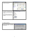
2-6 USB Uninstallation............................................................................................................. 10
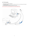
2-7 PC Connection .................................................................................................................. 11
CHAPTER 3 – OPTIONS INSTALLATION ..................................................................... 12
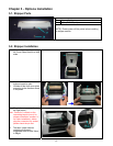
3-1 Stripper Parts..................................................................................................................... 12
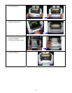
3-2 Stripper Installation............................................................................................................ 12
3-3 Stripper Installation Diagram ............................................................................................. 14
3-4 Cutter Parts ....................................................................................................................... 15
3-5 Cutter Installation............................................................................................................... 15
3-6 Extended Memory Parts.................................................................................................... 17
3-7 Extended Memory Installation ........................................................................................... 18
3-8 Ethernet Parts.................................................................................................................... 19
3-9 Ethernet Installation........................................................................................................... 19
CHAPTER 4 – LED MESSAGE DESCRIPTION............................................................. 21
4-1 LED Status ........................................................................................................................ 21
4-2 General Operation............................................................................................................. 21
4-3 Self-Test ............................................................................................................................ 21
4-4 Dump Mode....................................................................................................................... 23
4-5 Auto Sensing ..................................................................................................................... 23
4-6 Direct Thermal / Thermal Transfer Mode Switch............................................................... 23
4-7 Error Messages ................................................................................................................. 24
CHAPTER 5 – MAINTENANCE AND ADJUSTMENT ....................................................... 25
5-1 Thermal Print Head Cleaning ............................................................................................ 25
5-2 Thermal Print Head Balance Adjustment .......................................................................... 25
5-3 Print Line Adjustment ........................................................................................................ 26
5-4 Adjust the Cutter................................................................................................................ 26
5-5 Troubleshooting................................................................................................................. 27