


3
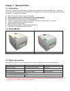
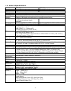
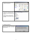
1-5. Communication Interface
Parallel Interface
Interface cable
:
Parallel cable compatible with IBM PC
Pin out
:
See below
PIN NO. FUNCTION TRANSMITTER
1
2-9
10
11
12
13
14
15
16
17
18
19-30
31
32
33
34-35
36
/Strobe
Data 0-7
/Acknowledge
Busy
/Paper empty
/Select
/Auto-Linefeed
N/C
Signal Gnd
Chassis Gnd
+5V,max 500mA
Signal Gnd
/Initialize
/Error
Signal Ground
N/C
/Select-in
host / printer
host
printer
printer
printer
printer
host / printer
host
host / printer
printer
host / printer
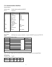
Serial Interface
Serial Default
Setting
:
9600 baud rate, no parity, 8 data bits, 1 stop bit, XON/XOFF protocol and RTS/CTS
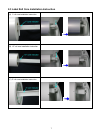
RS232 HOUSING (9-pin to 9-pin)
DB9 SOCKET DB9 PLUG
--- 1 1 +5V,max 500mA
RXD 2 2 TXD
TXD 3 3 RXD
DTR 4 4 DSR
GND 5 5 GND
DSR 6 6 DTR
RTS 7 7 N/C
CTS 8 8 RTS
RI 9 9 N/C
PC
PRINTER
NOTE: The total voltage output from parallel port and serial port altogether can not exceed 500mA.
USB Interface
Connector Type
:
Type B
PIN NO. 1 2 3 4
FUNCTION USBVCC D- D+ GND