


Connecting to the Network
Installation 3-5
3.5 CONNECTING TO THE NETWORK
This section provides the procedures for connecting unshielded twisted pair (UTP) segments to the
modules.
To make connections to an optional HSIM installed in the HSIM slot of a SmartSwitch, refer to the
instructions shipped with that device.
When facing the front panel of a 6E233-49 SmartSwitch, the top-left RJ21 is the connector for
10BASE-T ports 1 through 12; bottom left, ports 13 through 24; top-right, ports 25 through 36;
and bottom-right, ports 37 through 48. All 48 ports have internal crossovers.
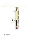
To connect an RJ21, proceed as follows:
1. Ensure that the device connected to the other end of the segment is powered ON.
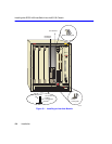
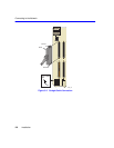
2. If using an RJ21 straight connector, plug it into the appropriate RJ21 port as shown in
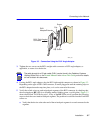
Figure 3-2, or if using the RJ21 right-angled adapter supplied with the device, insert it as shown
in Figure 3-3. The RJ21 right-angled adapter enables the cables to be dressed closely along the
front of the device.
NOTE
NOTE
NOTE
NOTE
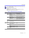
If the device is being installed in a network using SmartTrunking, there are rules
concerning the cable connections and port configurations that must be followed for
SmartTrunking to operate properly. Before connecting the cables, refer to the Cabletron
Systems
SmartTrunk User’s Guide
for the configuration information.