Connecting to the Network
Installation 3-7
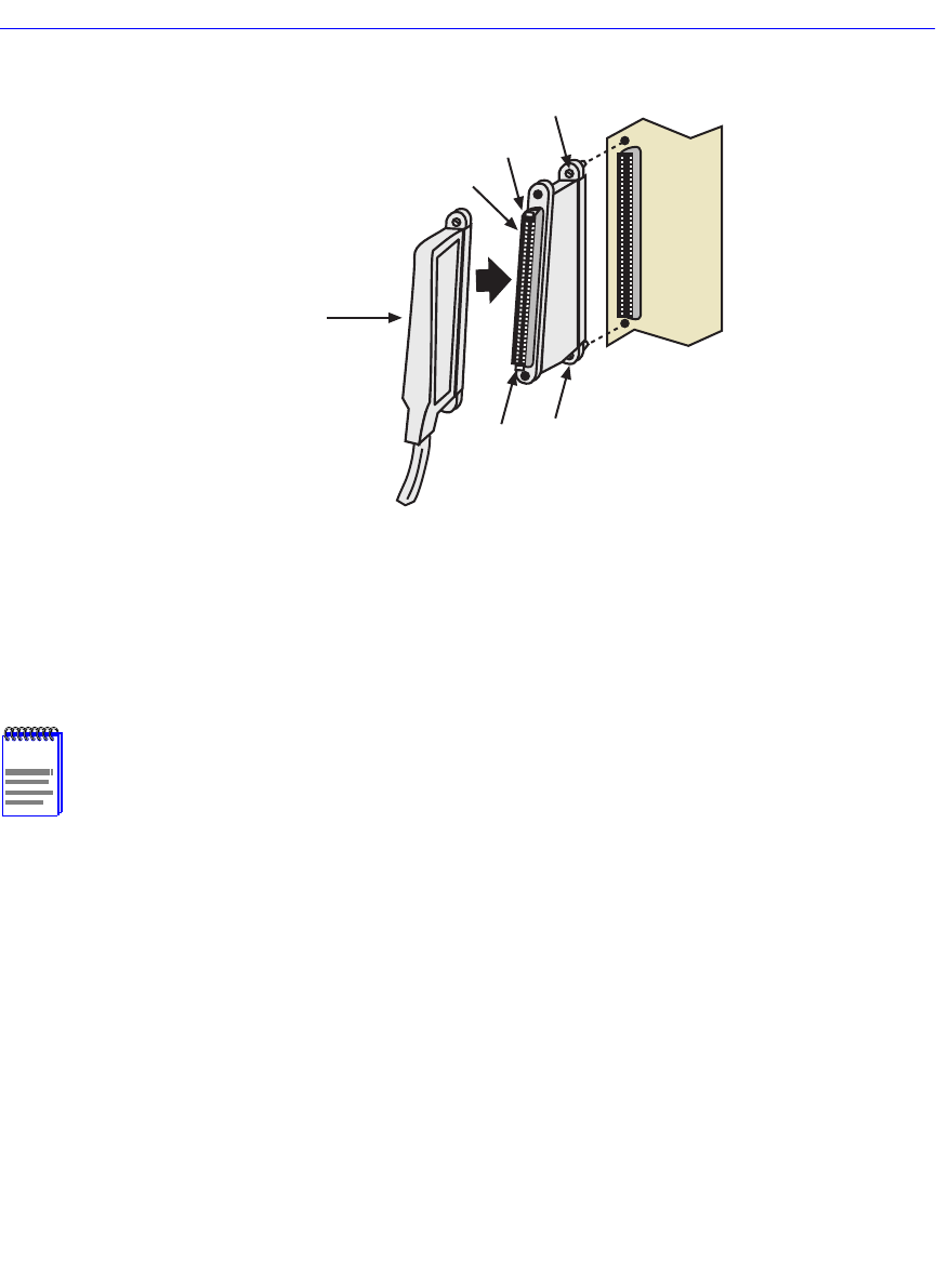
Figure 3-3 Connection Using the RJ21 Angle Adapter
3. Tighten the two screws on the RJ21 straight cable connector or RJ21 angle adapter, as
applicable, to secure it to the device.
4. If using the RJ21 angle adapter, plug the RJ21 right-angled connector as shown in Figure 3-3.
Depending on the type of RJ21 cable connector, it can be plugged in until the retaining clips on
the RJ21 adapter/extender snap into place, or it can be secured with screws.
5. Verify that a link exists on each twisted pair segment of the RJ21 connector by checking that
the associated port RX LED is on (flashing amber, blinking green, or solid green). Figure 3-3
shows the RX and TX LEDs for port 1. If any of the RX LEDs are off, perform the following
steps to check the associated twisted pair segment. The problem is resolved when the Link LED
comes on.
a. Verify that the device at the other end of the twisted pair segment is on and connected to the
segment.
NOTENOTENOTENOTE
The cable pinouts for a 25-pair cable (RJ21) can be found in the Cabletron Systems
Cabling Guide
. Refer to the Related Manuals in the About This Guide preface for details
on how to obtain this document.
2693_100
Screw
Screw
Clip
Clip
RJ21
Adapter/Extender
RJ21 Right-Angled
Connector


