


Chapter 5: Local Management
5-62 6E122-26, 6E132-25, 6E123-26 and 6E133-25 User’s Guide
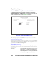
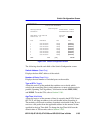
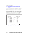
5.18 SWITCH CONFIGURATION SCREEN
The Switch Configuration screen, Figure 5-24, provides the basic setup
options to make a switch operational in your network.
Access the Switch Configuration screen from the Module Configuration
Menu screen by using the arrow keys to highlight the SWITCH
CONFIGURATION field and pressing ENTER. The Switch
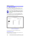
Configuration screen, Figure 5-24, displays ports 1 through 8. To view or
edit the fields for ports 9 to 16, highlight [9-16] at the bottom of the
screen and press the ENTER key. Perform the function again to view or
edit ports 17 to 24, and once again to view or edit ports 25 to 30.
NOTE
The Switch Configuration screen will not be available if the
operational mode of the module has been set to SECURE
FAST VLAN. This screen may only be used by modules
configured to operate as traditional or 802.1Q switches.
NOTE
Ports 25 and 26 on the Switch Configuration screen represent
the optional Fast Ethernet Interface Modules available for the
6E12X-26.
Port 25 on the Switch Configuration screen represents the
optional HSIM available for the 6E13X-25.
Ports 27 through 30 (6E12X-26) or 26 through 29 (6E13X-25)
on the Switch Configuration screen represent the backplane
connections that the module has with the 6C105 chassis. The
module has a direct connection to every other slot in the
chassis.