


Appendix C: Mode Switch Bank Settings and Optional Installations
C-6 6E122-26, 6E132-25, 6E123-26 and 6E133-25 User’s Guide
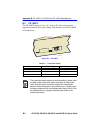
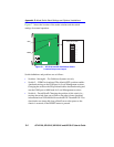
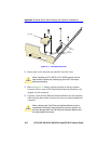
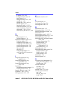
Figure C-3 Coverplate Removal
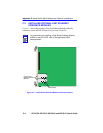
2. Remove the screw from the rear standoff. Save the screw.
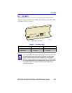
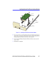
3. Refer to Figure C-4. Gently pull the faceplate of the host module
forward to allow room for the Fast Ethernet Interface Modules to be
aligned over the connector.
4. Carefully lower the Fast Ethernet Interface Module onto the standoffs
while inserting the module connector into the associated motherboard
connector.
!
CAUTION
When installing an FE-100FX or FE-100F3 module into the
host module, remove the rubber plug on the SC connector
before proceeding.
!
CAUTION
When inserting the Fast Ethernet Interface Module into the
motherboard connector ensure that the pins do not bend, as
this can damage both the Fast Ethernet Interface Module and
the motherboard connector.
Front
Standoffs
Rear
Standoff
Coverplate
25
26