


Chapter 3: Installation
3-10 6E122-26, 6E132-25, 6E123-26 and 6E133-25 User’s Guide
b. Verify that the RJ21 connectors on the twisted pair segment have
the proper pinouts and check the cable for continuity.
c. Check that the twisted pair connection meets the dB loss and cable
specifications outlined in Chapter 2.
If a link is not established, contact the Cabletron Systems Global Call
Center. Refer to Section 1.6, Getting Help, for details.
6. Repeat steps 1 through 4, above, until all connections have been made.
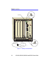
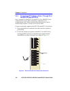
3.5.3 Connecting a Twisted Pair Segment to the
FE-100TX
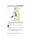
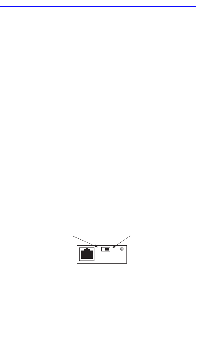
An FE-100-TX installed in port 25 and/or 26 has an internal crossover
switch. When connecting a workstation, use a straight-through cable and
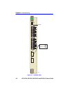
set the Fast Ethernet Interface Module crossover switch shown in
Figure 3-6 to the crossed over position marked with X. When connecting
networking devices, such as another bridge, repeater, or router, use a
straight-through cable and set the Fast Ethernet Interface Module
crossover switch shown in Figure 3-6 to the not crossed over position,
marked with =.
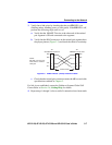
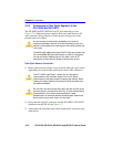
A schematic of a crossover cable is shown in Figure 3-6. If the wires do
not cross over, use the switch on the FE-100TX to internally cross over
the RJ45 port. Figure 3-6 shows how to properly set the FE-100TX
crossover switch.
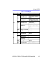
Figure 3-6 FE-100TX Crossover Switch
Position X
(crossed over)
1. RX+
2. RX-
3. TX+
4. NC
5. NC
6. TX-
7. NC
8. NC
Position =
(not crossed over)
1. TX+
2. TX-
3. RX+
4. NC
5. NC
6. RX-
7. NC
8. NC
FE-100TX
10
16651_05
100
=
x