


Chapter 5: Local Management
5-4 6E122-26, 6E132-25, 6E123-26 and 6E133-25 User’s Guide
5.3.2 Connecting an Uninterruptible Power Supply
(UPS)
If the 6C105 chassis is connected to an American Power Conversion
(APC) UPS for protection from a loss of power, a connection from the
COM port of a module to the UPS can be made to monitor the status of
the UPS. To use the COM port for this purpose, it must be reconfigured to
support the UPS application. This procedure is performed from the
General Configuration screen of the interface module. Section 5.15.11,
Configuring the COM Port, provides detailed instructions on
configuring the COM port for UPS applications. Refer to the UPS
documentation for details on how to access the status information.
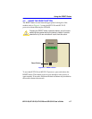
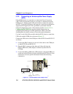
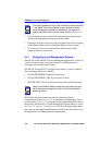
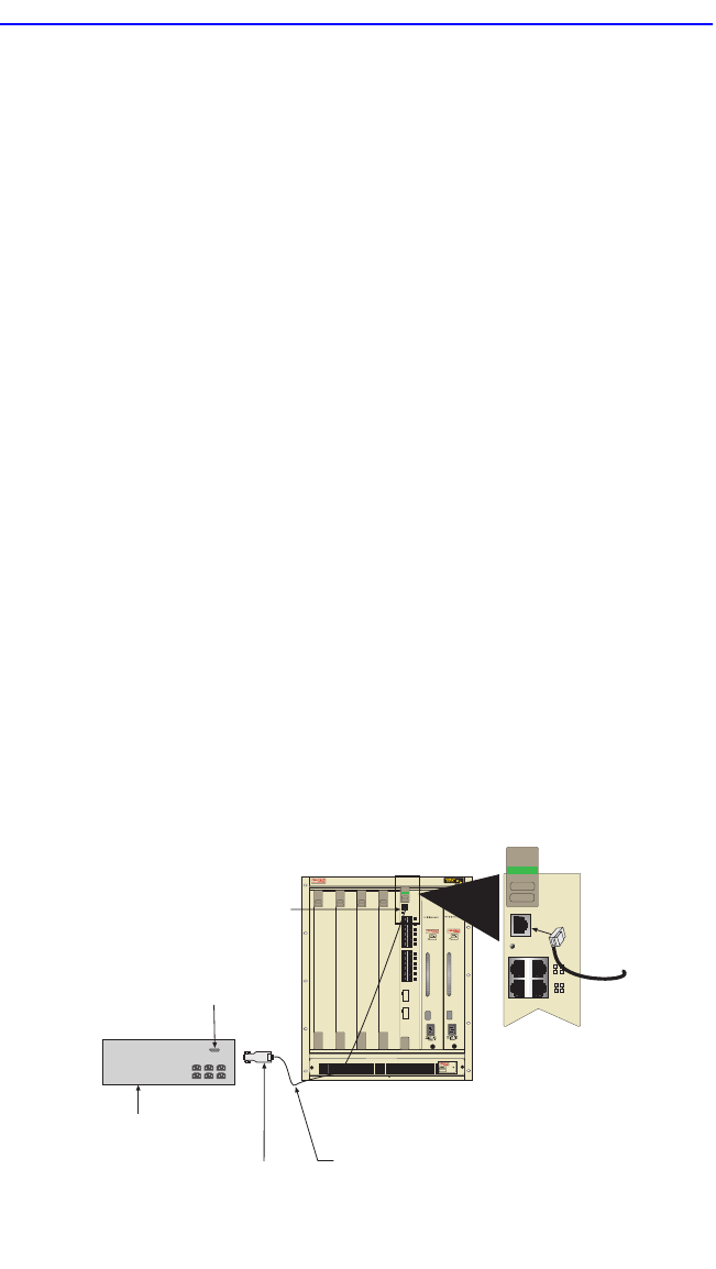
Use the Console Cable Kit provided with the 6C105 chassis to attach the
UPS to the module COM port as shown in Figure 5-2.
Connect the UPS device to the COM port of the 6E12X-26 and 6E13X-25
as follows:
1. Connect the RJ45 connector at one end of the cable to the COM port
on the 6E12X-26 and 6E13X-25.
2. Plug the RJ45 connector at the other end of the cable into the
RJ45-to-DB9 male (UPS) adapter, Cabletron Systems Part No.
9372066.
3. Connect the RJ45-to-DB9 male (UPS) adapter to the female DB9 port
on the rear of the UPS device (refer to the particular UPS device’s user
instructions for more specific information about the monitoring
connection).
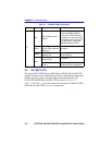
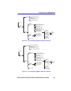
Figure 5-2 Uninterruptible Power Supply (UPS)
RJ45 COM Port
RJ45-to-DB9
UPS Adapter
UPS Device
DB9 Port
UTP Cable
With RJ45 Connectors
196051
1
2345
PS1
PS2
12
1413
25
26
COM
CPU
34
56
78
910
1112
1516
1718
1920
2122
2324
6E122-26
Ethernet
Reserved for FEPIM
Reserved for FEPIM
12
COM
CPU
34
6E122-26
Ethernet