


CONNECTING TO THE NETWORK
Page 4-1
CHAPTER 4
CONNECTING TO THE NETWORK
This chapter outlines the procedure for connecting the SEHI to your
network. Ensure that your network meets the guidelines and
requirements outlined in Chapter 2, Installation Requirements/
Specifications, before installing the SEHI to your network.
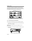
4.1 CONNECTING THE SEHI TO THE NETWORK
The procedure for connecting network segments to the SEHI varies
depending on the media and ports being connected. Refer to the
following list and perform the procedure described in the subsections
that apply to your SEHI:
• Network Ports, SEHI-22/24 4.1.1
• Network Ports, SEHI-32/34 4.1.2
• EPIM-T 4.1.3
• EPIM-F1, F2, F3 4.1.4
• EPIM-C 4.1.5
• EPIM-A 4.1.6
• EPIM-X 4.1.7
Prior to connecting the network cabling check the connectors for the
proper pinouts as shown in Chapter 2.
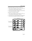
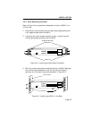
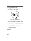
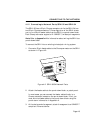
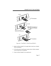
4.1.1 Connecting to Network Ports, SEHI-22 and SEHI-24
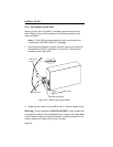
You attach unshielded twisted pair segments to the RJ45 Network
Ports on the front panel of the SEHI. Each twisted pair port on the
SEHI incorporates a Polarity Detection and Correction feature. The
Polarity Detection and Correction feature allows the SEHI to pass
data regardless of the polarity of the twisted pair segment’s receive
link. Operating in this condition is not recommended and if this
condition is discovered, the segment should be removed from the
network and wired correctly by a technician.