


RF400 Series Spread Spectrum Data Radio/Modems
3
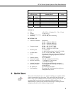
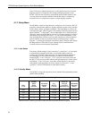
Quiescent Current in Standby Modes*
Avg. Quiescent
Current (mA)
Advanced Setup
Standby Mode
Standard
Setup
RF400/
RF410 RF415
24.0 33.0 0 (no duty cycling) 1
3.9 5.5 3 2
2.0 2.8 4 3
1.1 1.5 5
0.64 0.84 6
0.40 0.50 7 4
* Not receiving a signal nor transmitting
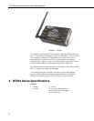
PHYSICAL
• Size 4.75 x 2.75 x 1.3 inches (12.1 x 7.0 x 3.3 cm)
• Weight 0.5 lbs (225 g)
• Operating temp. range –25°C to +50°C
• Humidity 0 to 95% RH, non-condensing
RF/INTERFACE
• Transceiver modules MaxStream
RF400 – 9XStream XO9-009
RF410 – 9XStream XH9-009
RF415 – 24XStream X24-009
• Frequency bands RF400 – 910.5 to 917.7 MHz
RF410 – 920.0 to 927.2 MHz
RF415 – 2.45015 to 2.45975 GHz
• Interface ports 1) CS I/O 9 pin
2) RS-232 9-pin (4 wire: Tx, Rx, CTS, GND)
• I/O Data Rates 38.4 K, 19.2 K, 9600, 4800, 1200 bps
• Mode Frequency hopping spread spectrum (FHSS), 25
hop channels, 7 hopping sequences, direct FM
frequency control
• Channel capacity 65,535 addresses
• Transmitter output 100 mW nominal (50 mW RF415)
• Receiver sensitivity −110 dBm at 10
-4
bit error rate
(−104 dBm for RF415)
• Antenna impedance 50 Ω, unbalanced (SMA male connector)
• Interference reject 70 dB at pager and cellular phone frequencies
(RF400/RF410)
• RF packet size up to 64 bytes, half-duplex
• Error handling RF packet CRC failure detection/rejection or
configurable retry levels
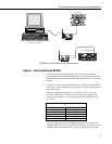
3. Quick Start
This section is intended to serve as a “primer” enabling you to quickly build a
simple system and see how it operates. This section describes in four steps
how to set up a pair of RF400s in a direct connect, point-to-point network. We
recommend that you do this before undertaking field installation. For
additional help on point-to-point networks and for help on creating point-to-
multipoint networks, refer to Software Setup Section 5.