


Appendix I. Phone to RF400 Series
I-3
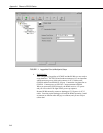
PC208W SETUP
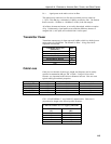
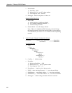
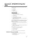
a. Network Map
COM1
Modem1
Generic1
CR10X_1
CR10X_2
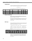
b. COM port - default settings
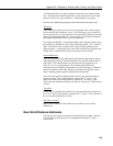
c. Phone Modem
1) Baud Rate – 9600
2) Modem Pick List – per PC’s phone modem
3) Extra Response Time – 2000 ms
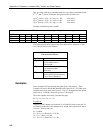
d. Generic Modem
1) Dialed Using phone # at base site
2) √ Make DTR Active and √ Hardware Flow Control
e. Datalogger 1
1) Dialed Using Generic Modem Dial String:
D1000T"---"R"OK"9200T"ATDT0001^m"R"OK"1200T"ATCN
^m"R"OK"1200
2) Set up scheduled collections as desired.
f. Datalogger 2
1) Dialed Using Generic Modem Dial String:
D1000T"---"R"OK"9200T"ATDT0002^m"R"OK"1200T"ATCN
^m"R"OK"1200
2) Set up scheduled collections as desired.
“0001” in the first ATDT command is the hexadecimal representation of
the combined Network Address / Radio Address chosen for this example
(i.e., Network Address = 0, Radio address = 1). The RF400 Setup Menu
calculates and displays this number for you in Standard Setup as “0001h”.
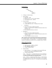
RF400 CONFIGURATION
a. Base RF400
1) Active Interface: “COM2xx to RF400”
2) AT Command Character: “-”
3) All other settings: defaults
b. Remote RF400s
1) Radio Addresses: 1, 2, etc. (unique for each remote RF400 and
must agree with respective RF400Remote settings)
2) All other settings: default
Note 1: Using a non “+” Command Character for the base RF400 is
necessary so the phone modem in the path passes the AT commands
on to the base RF400 rather than responding to them.
Note 2: If there is a neighboring RF400 network, you should change
the Hopping Sequence of base and remote RF400s to a new setting to
avoid interference (see Section 5.3.1 for method to detect neighboring
network).