


RF400 Series Spread Spectrum Data Radio/Modems
4
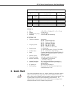
For this system you will need the following hardware or the equivalent:
1. Two RF400s
2. Two RF400 antennas
3. AC adapter (Item # 15966 or part of kit #14220)
4. Serial cable (6 ft.) for PC COM port to RF400 RS-232 port (Item # 10873
or part of Item # 14220)
5. SC12 cable (included with RF400)
6. Datalogger (CR10X, CR510, or CR23X)
7. Field Power Cable (Item # 14291) if datalogger or wiring panel doesn’t
have 12 V on pin 8 of CS I/O port
You will also need:
1. An IBM
TM
compatible PC with one available COM port
2. LoggerNet or PC208W installed
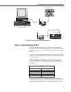
Step 1 – Set Up Base RF400
a. Connect an antenna (or antenna cable with yagi or omni directional
antenna attached) to the RF400 antenna jack. Any RF400 antenna will
work at close range in any orientation. The main objective is to provide
an antenna. If you should transmit without an antenna attached, there will
be no equipment damage as the transmitter is protected against load
mismatch. The separation between the base RF400 antenna and the
remote RF400 antenna can be any convenient distance.
b. Connect 6 ft. serial cable from PC COM port to base RF400 RS-232 port.
c. Plug AC adapter into AC outlet and plug barrel connector into base
RF400 “DC Pwr” jack. You will see the red “Pwr/TX” LED light
immediately followed by the green RX LED in about 5 seconds. The
green LED goes off after a second and the red after ten seconds indicating
a successful power-up. The red LED then begins to flash on and off. The
red LED flashes once every half second in the default “< 4 mA, ½ sec
Cycle” standby mode as the RF400 wakes up briefly and listens for RF
transmissions with an average current consumption less than 4 mA.
d. Use default settings of RF400.