RF400 Series Spread Spectrum Data Radio/Modems
6
Current dataloggers and wiring panels (not mentioned in Table 1) provide
12 V on pin 8. For older products not listed, check for 12 V between CS
I/O connector pin 8 and pin 2 (GND) or contact Campbell Scientific.
c. Use default settings of RF400.
Step 3 – LoggerNet/PC208W Set-up
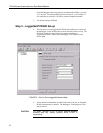
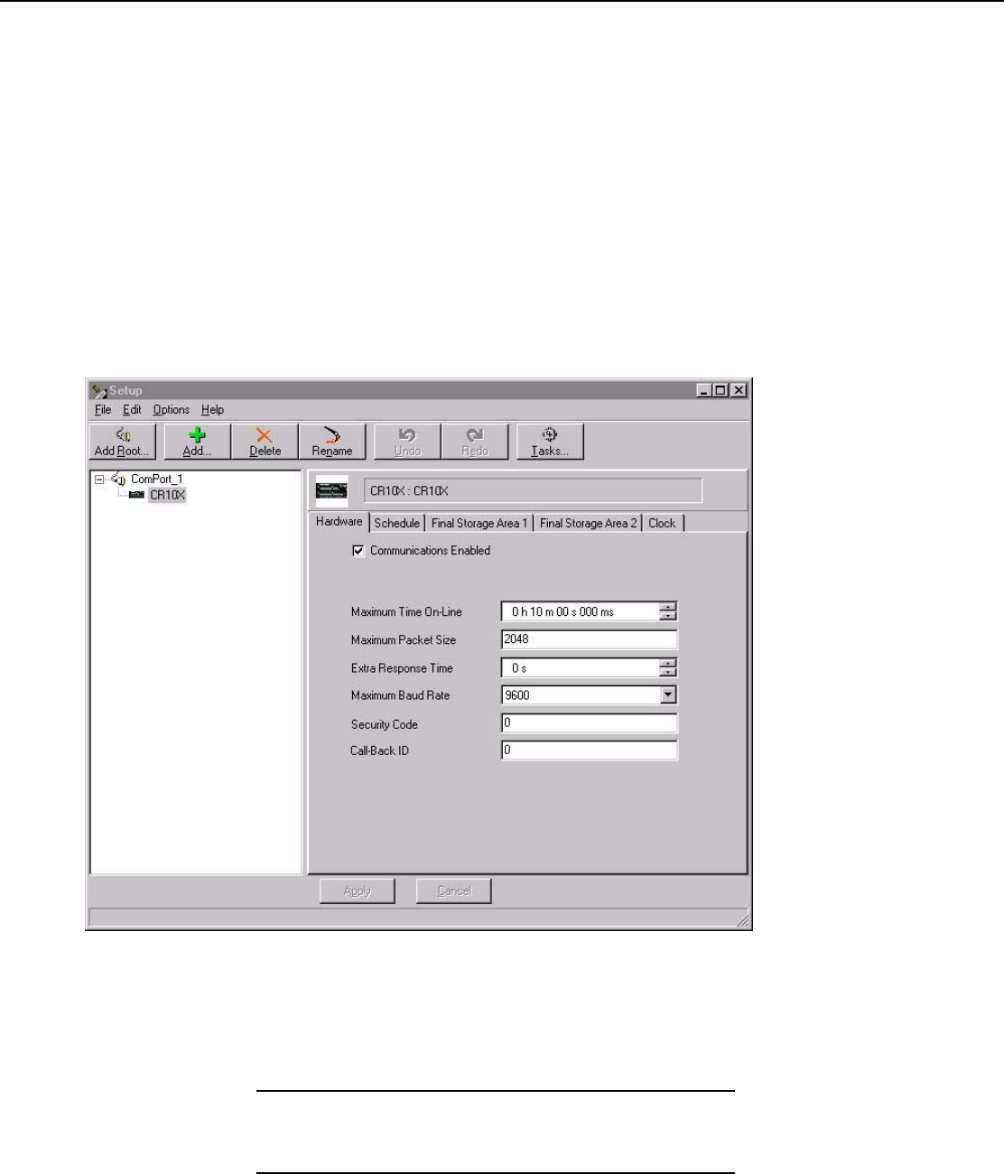
a. The next step is to run LoggerNet/PC208W and configure it to connect to
the datalogger via the RF400 point-to-point network you have set up. The
RF400 in a point-to-point network can operate transparent to
LoggerNet/PC208W. Simply add a datalogger to a COM port in the
Device Map.
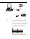
FIGURE 3. Point-to-Point LoggerNet Network Map
b. Set the Maximum Baud Rate for 9600 baud which is the rate at which the
RF400 communicates by default. The datalogger “Extra Response Time”
can be left at 0.
For safety, maintain 20 cm (8 inches) distance between
antenna and any nearby persons while RF400 is
transmitting.
CAUTION


