


B-1
Appendix B. Setup Menu
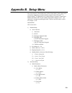
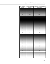
Here is the structure of the RF400 series’ built-in Setup Menu system which can be
accessed by configuring a terminal emulator program such as Procomm
TM
or
HyperTerminal
TM
to 9600 baud (8-N-1) and pressing the “Program” button on the
RF400 with RF400’s RS-232 port cabled to appropriate COM port of PC. Also
displayed is a number representing the radio’s software and RF module versions.
For example: 6.425.
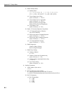
MAIN MENU
SW Version 6.425
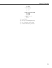
1) Standard Setup
a) Active Interface
i) Auto Sense
ii) RS-232
iii) Datalogger Modem Enable
iv) Datalogger SDC
(not for Table Based Loggers)
v) Datalogger CSDC
(only for Table Based Loggers)
vi) COM2xx to RF400
b) Net Address (0 – 63)
c) Radio Address (0 – 1023)
d) Hopping Sequence ( 0 - 6)
e) Standby Mode (select one of the following)
i) <24 mA Always On
ii) < 4 mA 1/2 sec Cycle
iii) < 2 mA 1 sec Cycle
iv) < .4 mA 8 sec Cycle
2) Advanced Setup
a) Radio Parameters
i) Radio Address Parameters
(1) Net Address
(0 – 63)
(2) Radio Address
(0 – 1023)
(3) Net Address Mask
(0 – 3fh)
(4) Radio Address Mask
(0 – 3ffh)
(5) Hop Table
(0 – 6)