


E-1
Appendix E. RF400 Series Port Pin
Descriptions
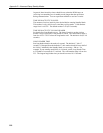
RS-232 Port
The “RS232” port is a partial implementation of RS-232C. It is configured as
Data Communications Equipment (DCE) for direct cable connection to Data
Terminal Equipment (DTE) such as an IBM-PC serial port.
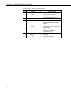
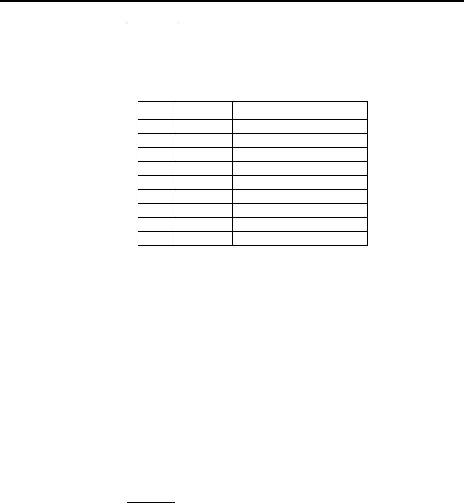
RS-232 CONNECTOR, 9-PIN D-SUB FEMALE
PIN I/O DESCRIPTION
1
2O TX
3I RX
4
5 GND
6
7
8O CTS
9
I = Signal Into the RF400, 0 = Signal Out of the RF400
Only CTS is implemented for flow control. If data arrives (say from a PC)
faster than the RF400 transmits it, the RF400 will de-assert CTS when the 640
byte port buffer is full. If the PC continues to send data, the buffer will accept
it and may wrap around over-writing oldest data. PC208W and LoggerNet
monitor CTS to prevent buffer over-run.
The RF400 can transmit RF packets slightly in excess of 9600 baud. When RF
packets are received by the RF400, that data is immediately sent to the “active
interface” port without flow control (no RTS).
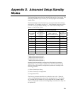
For many applications the RF400 works fine with no flow control. The need
for flow control arises when longer standby modes are used, where more data
could be sent than the 640 byte buffer can hold before transmittal. For
example, if the RF400s are in Standby Mode 6 (see Appendix D), an RF400
needs to buffer incoming RS-232 data for up to 8 seconds while waiting for
the other RF400 to wake up before transmitting it. Also, if the RF400 is doing
a lot of retries, that can take extra time and require flow control to avoid buffer
over-run.
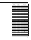
CS I/O Port
The CS I/O port is Campbell Scientific's input/output port. It is not a standard
RS-232 pin-out. The following table provides pin-out information on the port
when connected to a datalogger.