


J-1
Appendix J. Monitor CSAT3 via RF400
Series
Procedure for installing a pair of RF400 series spread spectrum radios for
monitoring a CSAT3 system at a distance. This function has traditionally been
implemented by running a short haul modem cable between CSAT3 and PC.
HARDWARE REQUIREMENTS
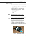
• Two RF400s (mounting bracket option available)
• Two RF400 antennas (and possibly cables, see Section 4.4 for
options)
• Base Cable/Power Kit Item #14220 (contains 120V AC Adapter and
6 ft. PC to RF400 serial cable).
• Remote station 12V Field Power Cable Item # 14291 or (if 120VAC
is available), AC adapter Item # 15966
• 9 pin male to 9 pin male null-modem serial cable (CSI Item # 14392)
• PC with HyperTerminal
TM
or Procomm
TM
for RF400 setup (if
neighboring RF400s).
• Spare PC COM port (COMx)
RF400 SETUP
(1) Plug AC adapter into 120VAC outlet; plug barrel connector into
“base” RF400 and wait 10 seconds for RF400 to initialize.
(2) Connect 6 ft. cable (from base kit) between PC COM port and base
RF400 RS-232 port.
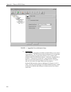
(3) Run Hyperterminal
TM
or Procomm
TM
on PC and configure for
(a) Baud rate: 9600, 8-N-1
(b) Flow control: none
(c) Emulation: TTY
(d) ASCII
(e) COMx (direct connect)
Note: if using Hyperterminal
TM
it will probably be necessary to do a
Call Disconnect and then a Call Connect for new settings to take
effect.
(4) Press “Program” button on RF400
The following text should be written to the terminal screen
Main Menu
SW Version XX.YYY
(1) Standard Setup
(2) Advanced Setup
(3) Restore Defaults
(4) Show All Current & Default Settings
(5) Save All Parameters & Exit Setup
(9) Exit Setup without Saving Parameters
Enter Choice: