EdgeFLEX 600 - Release 2.0 2-3
EdgeFLEX 600 Installation
Chassis Components
Chassis Components
Fan Tray, System Interfaces, and Power Supply Units
The following components are standard features of the EdgeFLEX 600 chassis:
System interfaces (Ethernet, RS-232, etc.)
Air filter
Fan tray assembly (located in the front right of chassis)
Cable management flange at the left front
Bezel at the right front of the chassis
DC power input connectors (located on the modular Power Supply Unit at the top of the chassis)
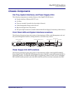
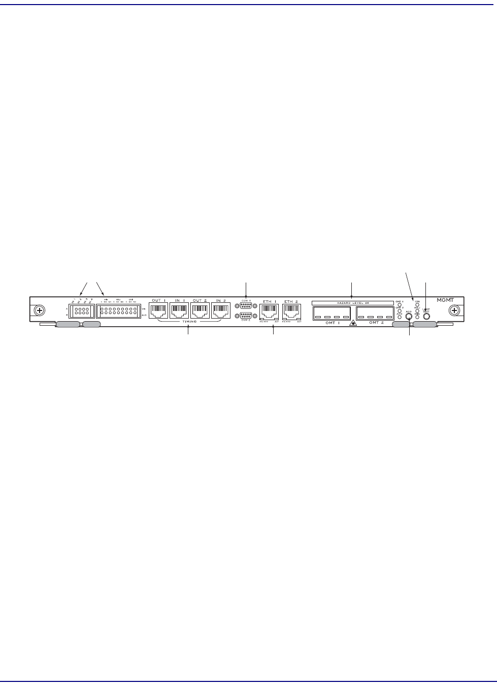
Front Panel LEDs and System Interfaces Locations
The following illustration shows the location of the alarm/status LEDs on the Management card, and
the system management interfaces, timing interfaces, and alarm relay contacts.
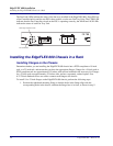
Power Supply Unit LED Locations
The following illustration shows the location of the alarm/status LEDs on the EdgeFLEX 600 DC
Power Supply Units. The PSU OK LED indicates the status of the PSU; green indicates that the PSU is
functioning properly, red indicates that the PSU is experiencing a fault or (in the case of a redundant
PSU with the system powered by the other PSU) that DC power has not been connected to the PSU.
Management Ethernet Ports 1 & 2
Alarm Relay Contact Blocks
OMT Receptacles 1 & 2
Alarm Cutoff Button
Lamp Test Button
System Alarm LEDs
RS-232 Serial Management Ports 1 & 2
Timing Inputs and Outputs


