2-4 EdgeFLEX 600 - Release 2.0
EdgeFLEX 600 Installation
Installing the EdgeFLEX 600 Chassis in a Rack
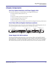
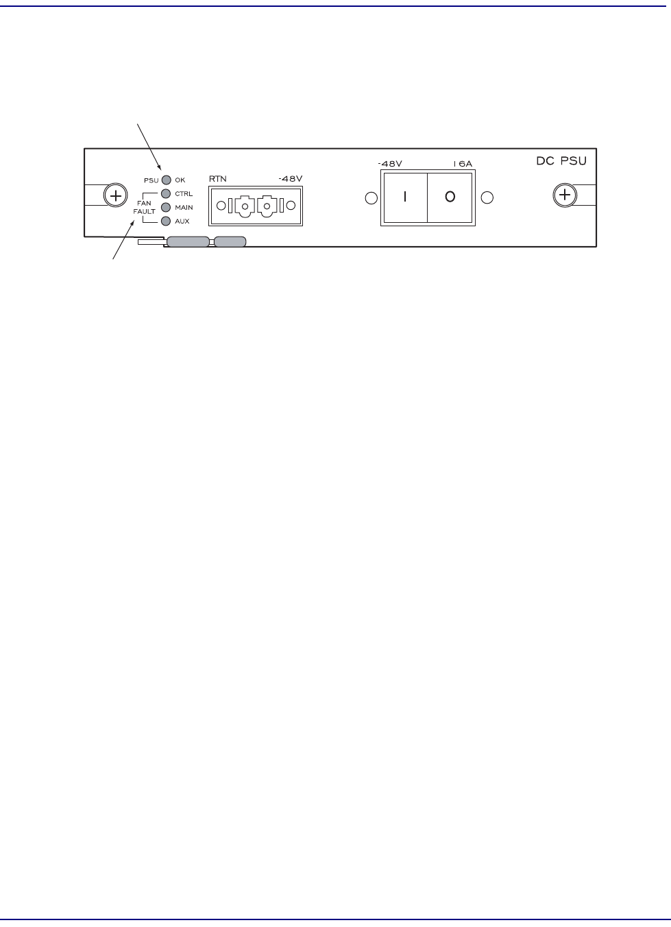
The Fan Fault LEDs indicate the status of the fan trays installed in the EdgeFLEX 600. Each PSU has
a Fan Controller built in and the two PSUs share control over the two Fan Tray Units. The CTRL LED
indicates that the Fan Controller circuit on the PSU is operating correctly; the MAIN and AUX LEDs
indicate the status of each Fan Tray Unit.
Installing the EdgeFLEX 600 Chassis in a Rack
Installing Flanges on the Chassis
Determine whether you are installing the EdgeFLEX 600 chassis into a ETSI-compliant or 19-inch
rack, or a 23-inch rack, and ensure that you have the appropriate flanges. Flanges for a 19-inch rack or
ETSI-compliant rack are approximately 0.5 inches wide and are included in the accessory kit. Flanges
for a 23-inch rack are approximately 4.5 inches wide, and are a separately ordered option. Four
6-32
¼-inch flathead screws are used to connect each flange to the chassis.
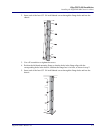
To install 19 or 23 inch flanges on the EdgeFLEX 600 chassis, perform the following steps:
1. Position the right-hand mounting flange so that the holes in the flange align with the
corresponding holes in the chassis, and that the flange face is in front, as shown in step 2.
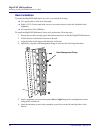
Power Supply Unit Status Indicator
Fan Fault Indicators


