EdgeFLEX 600 - Release 2.0 2-17
EdgeFLEX 600 Installation
Powering Up and Checking LEDs
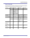
Check I/O Card LEDs
The I/O cards contain LEDs that represent card and/or port status, depending on the cards installed in
the EdgeFLEX 600. Refer to the illustration in Card LED Locations, on page 2-15 for the location of
the LEDs. The following table shows the states and interpretation of the LEDs.
Card Type LED Label Description Normal State Alarm State
Any Power Card has powered up Green On (Red), or Off
Fault Card is experiencing a
fault condition
Off On (Red)
Active (Act) Card is Active
member of a
redundant pair
Standby (Sby) Card is Standby
member of redundant
pair
Quad Gigabit
Ethernet SCPX
1 - 4 Ports 1 - 4 Green (Link), Blinking
(Activity)
On (Amber), or
Off
Dual Gigabit Ethernet 1 - 2 Ports 1 and 2 Green (Link), Blinking
(Activity)
On (Amber), or
Off
Octal Fast Ethernet (left LED) Speed Green = 100 Mbps
Off = 10 Mbps
On (Red), or Off
(right LED) LINK • Green = Link without
Activity
• Blinking = Link with
Activity
On (Red)
Quad SONET/SDH
or 84/63 CESoP
Server
OC-3/OC-12
STM-1/STM-4
1 - 4 Ports 1 - 4 Green (Link) Amber (LOS), or
Off
Quad SONET/SDH
SCPX
OC-12/48
STM-4/STM-16
1 - 4 Ports 1 - 4 Green (Link) Amber (LOS), or
Off
16 port T1/E1
(all varieties)
1 - 16 Ports 1 - 16 Green (OK) Red (Fault), or Off
(unprovisioned)


