


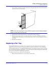
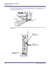
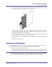
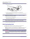


A-4 EdgeFLEX 600 - Release 2.0
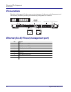
Connector Pin Assignments
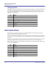
Alarm Inputs Pinout
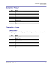
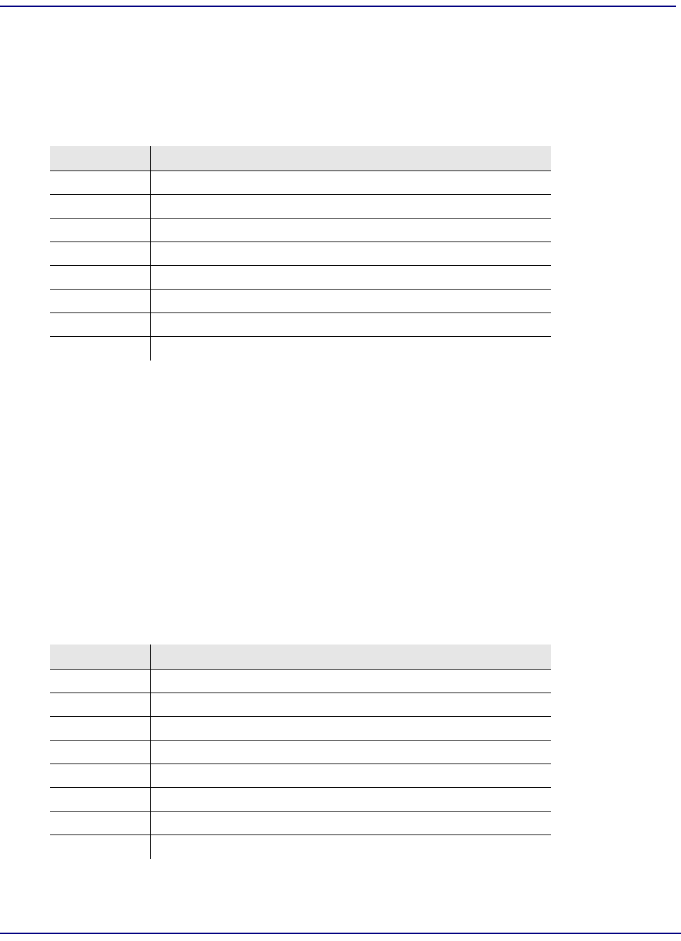
Timing Out Ports
The EdgeFLEX 600’s two Timing Out ports provide only timing output pins, as shown in the following
table. When the EdgeFLEX 600 is powered, the timing output is synchronized to the input timing
signal. When the EdgeFLEX 600 is not powered, the input timing signal is connected directly to the
output pins as a pass through.
Alarm Inputs Pinout
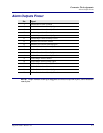
The alarm inputs are polarity insensitive; the A and B designations in the following table simply
represent the labeling on the management card itself.
The circuitry associated with these pins will sense voltage and/or current changes on the two IN pins in
a set (i.e., pins 1 and 2 represent Input 1). The Voltage Threshold is 5-75Vdc and maximum current is
0.5 Amps.
The inputs are current limited and will never present a load greater than 2 milliamps to the source. The
platform is protected from excessive voltage at its input by a 0.5A non-user-serviceable fuse.
NO and NC status applies to a powered system only; when the system is powered down, NO becomes
NC as a fail-safe mechanism.
Pin Signal
1 Not used
2 Not used
3 Not used
4 BITS_OUT_TRING
5 BITS_OUT_TTIP
6 Not used
7 Not used
8 Not used
Pin Signal
1 Input 1 B
2 Input 1 A
3 Input 2 B
4 Input 2 A
5 Input 3 B
6 Input 3 A
7 Input 4 B
8 Input 4 A