


EdgeFLEX 600 - Release 2.0 2-15
EdgeFLEX 600 Installation
Powering Up and Checking LEDs
Powering Up and Checking LEDs
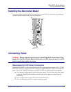
Powering Up the Chassis
After you install the power cables, system cables, and network cables, you are ready to power up the
EdgeFLEX 600. To power up the chassis, perform the following steps:
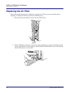
1. Ensure that the ground cable and all the power cables are installed and secure.
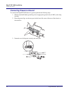
2. Apply DC power from the power source, as appropriate.
3. Turn the circuit breaker switch to ON.
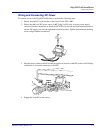
Turning on the circuit breakers applies power to all the components in the chassis. The system powers
up and the LEDs on the power supply and Management Card provide the operational status.
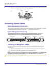
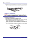
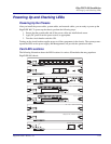
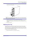
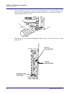
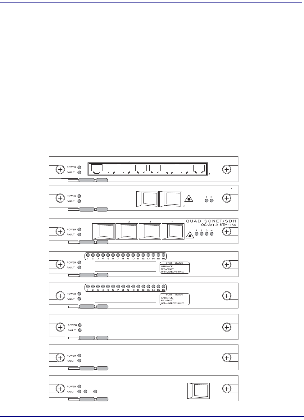
Card LED Locations
The following illustration shows the LED locations for various I/O modules that may populate a
EdgeFLEX 600 chassis.
84/63 CESoP SERVER
ACT/SBY
1
GIGABIT ETHERNET
10/100 ETHERNET
T1/E1 CESoP
T1/E1 MULTISERVICE
84/63 IMA / PACKET SERVER
16 T1/E1 CESoP SERVER