


E-64
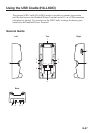
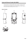
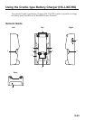
1 Terminal Detect
Switch
This switch detects when the IT-9000 is mounted correctly on the
Ethernet Cradle.
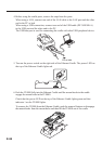
2 Mount Hooks These hooks are used to stabilize the IT-9000 when mounting it
on the cradle.
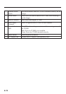
3 Removal Buttons Press when removing the IT-9000.
4
Power Supply/Data
Communication
Terminals
Power is supplied to the IT-9000 via these contacts. Also used for
data communication.
5 Power Indicator
LED
This LED indicates the power status and the mounting status of
the IT-9000.
Red: Power on, IT-9000 is not installed.
Green: Power on, IT-9000 mounted correctly.
6 Power Switch Turns the power on and off.
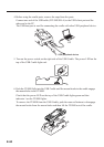
7 USB Client Port This port is used to transmit system data and fi le data (download,
upload) by connecting the Ethernet Cradle to a PC using a USB
cable (DT-380USB-A). The dedicated driver must be installed in
the PC before connecting the Ethernet Cradle to the PC.
8 USB Host Port This port is used to connect a corresponding USB peripheral
device.
9 LAN Port This port is used for connecting the cradle to a PC or hub via a
LAN cable so that system data and fi le data can be transmitted
(uploaded or downloaded).
The special driver software must be installed in the IT-9000.
10 LAN Connection
Status LED
This LED shows the status of the LAN connection.
Off: LAN cable not connected correctly.
Lit orange: LAN cable connected correctly.
11 LAN
Communication
Status LED
This LED shows the LAN operation status.
Off: No communication.
Blinking: Communication in progress.
12 Selector Switch This switch is used to switch between a USB connection and a
LAN connection.
LAN: LAN
A: USB host
B: USB client
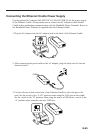
13 AC Adaptor Jack Connect the AC adaptor (sold separately) here.