


20
IV. Hardware Setup
IV. Hardware Setup
AP8000 Hardware Reference Guide
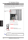
This server supports two processors which requires one retention mecha-
nism for each processor. Before installing the CPU, secure the mother-
board on the rubber pad and metal baseboard. (See page 18.)
When only one processor is used, the other Slot 2 connector must be termi-
nated with the provided front side bus termination module.
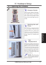
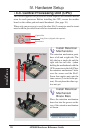
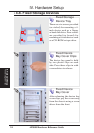
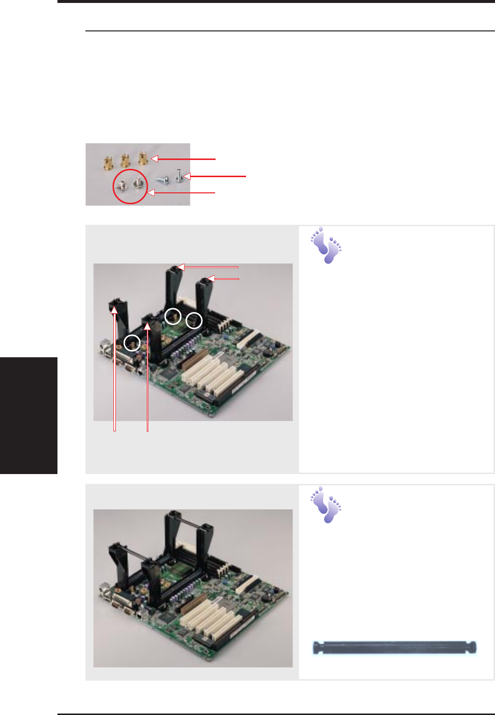
• 4-3. Central Processing Unit (CPU)
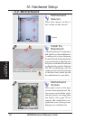
CPU
Captive Nut
Long Screw (aligned with spacers)
Short Screw
Install Retention
Mechanisms
The retention mechanism parts
have a left and a right side. The
left side has a single dot and the
right side has two dots (when
holding the motherboard with the
ATX connectors to the left). Place
the retention mechanisms’ holes
over the screws and the Slot2.
Screw four captive nuts onto the
inner screws (3 circled in the pic-
ture). Do not place the other cap-
tive nuts yet.
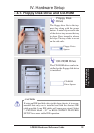
Two Dots
One Dot
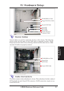
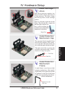
Install Retention
Mechanism
Brace Bars
Place the retention mechanism
brace bar into the groove on the
top of the retention mechanism
as shown.
Retention Mechanism Brace Bar