


11
LX505/LX605 User Manual
002-000232-01 Rev.1 (12-2009)
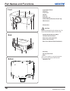
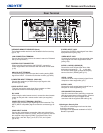
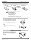
R/C JACK
When using the wired remote control, connect the wired remote
control to this jack with a remote control cable (not supplied)
(p.15).
USB CONNECTOR (Series B)
Use this connector when controlling a computer
with the remote control of the projector. Connect
the USB terminal of your computer to this
connector with the supplied USB cable (p.19).
AUDIO 2 JACK
Connect the audio output (stereo) signal from a
computer or video equipment (p.21).
VIDEO INPUT JACK
Connect the component or the composite video
output signal from video equipment to these
jacks (p.20).
CONTROL PORT CONNECTOR
When controlling the projector with RS-232C, connect the
control equipment to this connector with the serial control cable.
(p.19)
COMPUTER INPUT TERMINAL (DIGITAL)
Connect the computer output digital signal to this terminal. The
HDTV (HDCP compatible) signal can also be connected (pp.19-
20).
COMPUTER INPUT TERMINAL (ANALOG)
Connect the computer (or RGB scart) output signal to this
terminal (pp.19-20).
5 BNC INPUT JACKS
Connect the component or composite video output signal from
video equipment to VIDEO/Y, Pb/Cb, and Pr/Cr jacks or connect
the computer output signal (5 BNC Type [Green, Blue, Red,
Horiz. Sync, and Vert. Sync.]) to G, B, R, H/V, and V jacks
(pp.19-21).
Part Names and Functions
S-VIDEO INPUT JACK
Connect the S-VIDEO output signal from video
equipment to this jack (p.20).
AUDIO 1 JACK
Connect the audio output (stereo) signal from a
computer or video equipment (p.21).
AUDIO OUTPUT JACK
This jack outputs the audio signal from computer or video
equipment to external audio equipment (p.21).
Kensington Security Slot
This slot is for a Kensington lock used to deter
theft of the projector.
*Kensington is a registered trademark of ACCO
Brands Corporation.
INFRARED REMOTE RECEIVER (Back)
The infrared remote receiver is also located in the front and top
(pp.10, 15).
ANALOG OUT TERMINAL
This terminal can be used to output the incoming analog RGB
signal from INPUT 1-3 terminal to the other monitor (pp.19-20).
LAN CONNECTION TERMINAL
Connect the LAN cable (refer to the owner’s manual of “Network
Set-up and Operation”).
AUDIO 3 JACKS (L(MONO)/R)
Connect the audio output signal from video
equipment connected to or to this jack.
For a mono audio signal (a single audio jack),
connect it to the L (MONO) jack (p.21).
Rear Terminal