


Chapter 2 Cabling and Troubleshooting the CSS
Cabling the CSS 11501
2-4
Cisco 11500 Series Content Services Switch Hardware Installation Guide
78-13884-06
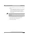
CSS 11501 Connectors and LEDs
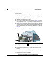
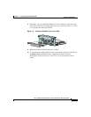
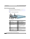
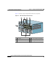
The CSS 11501 has all connectors and LEDs on the chassis front panel. Figure 2-1
illustrates the connectors and LEDs on the CSS 11501.
For information on the connector pinouts, refer to Appendix B, Cable Connector
Pinouts.
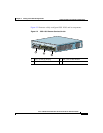
Figure 2-1 CSS 11501 Connectors and LEDs
1 Bicolor status LED
(green and red)
6 RJ-45 Ethernet
10BASE-T/100BASE-TX
connectors 1 through 8
1
1. The Ethernet Link/Act LED and Duplex LED are located at the top of each RJ-45 Ethernet
connector and are not visible in this illustration.
2 Amber status LED 7 LC-type SFP GBIC (optional)
3 RJ-45 RS-232 Console connector 8 Link LED for SFP GBIC
4 10-Mbps half-duplex Ethernet
management connector
9 RJ-45 RS-232 Diag connector for
field service diagnostic use only.
(A connector cover is provided.
Removing the cover voids the
warranty.)
5a PCMCIA slot 0 containing a flash
or hard disk
10 PCMCIA slot cover
5b PCMCIA slot 1 (shown empty) for
optional installation of a second
flash or hard disk
11 Recessed button (reserved for field
service use only)
CISCO 11500
SERIES
CONTENT SERVICES SWITCH
78930
DUPLEX
LINK/ACT
LINK
STATUS
PCMCIA
GE
CONSOLE
LINK DPLX
LINK DPLX
LINK DPLX
LINK DPLX
1
2
3
4
10/100
LINK DPLX
LINK DPLX
LINK DPLX
LINK DPLX
5
6
7
8
10/100
2
3
4
5b
7
10
11
5a
9
1
8
6