


2-23
Cisco 11500 Series Content Services Switch Hardware Installation Guide
78-13884-06
Chapter 2 Cabling and Troubleshooting the CSS
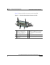
Connecting the Chassis to Ground
Tools and Supplies
The accessory kit shipped with the CSS contains the following items used in this
procedure:
• One 2-hole grounding lug (Panduit no. LCD6-10A-L)
• Two M5 screws for the grounding lug
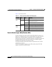
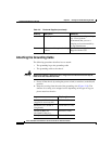
Table 2-8 lists the other tools, equipment, and supplies that you need to connect
system ground to the chassis. These are items that you must supply.
Table 2-8 Tools and Supplies
Quantity Description Comments
1 Number 2 Phillips screwdriver —
1 Wire stripping tool Choose a tool that does not nick
the wire.
Varies Grounding wire 6 AWG, 0.204 in. (5.18 mm)
recommended. The wire should
have applicable agency
approvals such as Telcordia.
Varies Screws to attach ground wire to
grounding point at site
Part requirements depend on
location.
1 or 2 2-hole grounding lug. Lug must
fit 6 AWG stranded copper or
37/24 flex cables. Each lug must
have two holes, centered
0.625 in. (1.587 cm) apart, and
must accept M5 screws.
One lug is supplied by Cisco
Systems in the accessory kit. The
supplied lug is for the router end
of the ground wire. You may
wish to use a lug other than the
one supplied. If you need a lug
for the facility end of the ground
wire, you must supply it.
Recommended types:
• Panduit no. LCD6-10A-L
(1 supplied in accessory
kit)
• Panduit no. LCC6-10A-L
(long barrel)
• Thomas & Betts no.
256-30695-1183(*4*)
• Burndy no. YA6CL2TC10