


2-17
Cisco 11500 Series Content Services Switch Hardware Installation Guide
78-13884-06
Chapter 2 Cabling and Troubleshooting the CSS
Cabling the CSS 11503 and CSS 11506 Modules
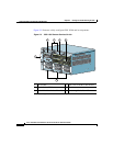
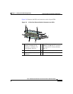
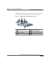
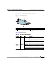
The GEM front panel LEDs indicate the network status for each of the connectors
(Link LEDs). Figure 2-7 illustrates the LEDs and connectors on a GEM.
Figure 2-7 Gigabit Ethernet Module Connectors and LEDs
1 Bicolor status LED (green and
red)
4 Link LED (next to its
corresponding SFP GBIC)
2 Amber status LED 5 Spring-loaded screw (one of two)
3 LC-type SFP GBIC (one of two) 6 Ejector (one of two)
59535
CSS5-10M-2GE
2 Gigabit Ethernet
GE 1
GE 2
LINK
LINK
STATUS
1
2
3
4
4
5
6