


5-13
Cisco Metro 1500 Series Hardware Installation Guide
78-10588-03
Chapter 5 Connecting Optical Cables
Connecting Fiber Channel or Gigabit Ethernet to a High-Speed Transparent WCM
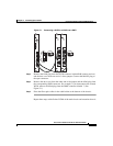
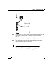
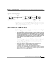
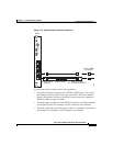
Figure 5-9 Attenuating Coupler
Figure 5-9 shows a conventional MiniSC to SC patch cable, plus the attenuating
coupler, which achieves the same effect as the attenuating single-mode patch
cable assembly with the built-in attenuation.
Other Limitations and Restrictions
The following limitations and restrictions for connecting fiber channel or Gigabit
Ethernet to a high-speed transparent WCM:
• The coupling facility currently requires that at least two LPARs be active for
the link to activate and that the link between the two sites be no longer than
15.5 mi (25 km). Installation of the card requires that an LPAR be cycled to
clear the loop condition created by the card. If only one LPAR is present, the
optical interface is cycled with the LPAR and the loop is once again
established.
• When using low-speed applications (200 Mbps and below) with high-speed
cards, the application is typically overdriven. As a workaround, add
attenuation to the signal coming from the local transmitter port of the
Cisco Metro 1500 series system.
• Do not use a multimode patch cable that has been attenuated using
core-shifted splicing to attenuate the signal coming from a
Cisco Metro 1500 series system. The system interface is always a
single-mode laser and the attenuation is not consistent or reliable. In addition,
for all interfaces, avoid air-gap attenuators, which have high back reflection
that may cause bit errors on the connection.
MiniSC (MUPC)
single-mode connector
SC
single-mode connector
5-dB
Attenuating
coupler
SMF
39363
5-dB