


Chapter 5 Connecting Optical Cables
Testing a Remote Link
5-16
Cisco Metro 1500 Series Hardware Installation Guide
78-10588-03
Testing a Remote Link
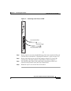
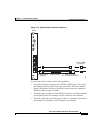
The remote loopback feature of the WCM allows you to test the remote optical
communications link without disconnecting the system. You must test the remote
link to verify that it meets the specifications to ensure proper operation. Tests may
already be available from the supplier of the fiber. If no report is available,
perform the tests to verify that parameters are within specifications.
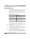
Table 5-1 lists the tests required for the remote link and the equipment required to
perform each test.
To test a remote optical communications link, follow these steps:
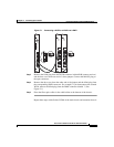
Step 1 Disconnect the local lines from the WCMs at both the local and remote systems
in the link to be tested.
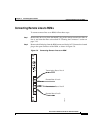
Step 2 Supply a modulated light to the local receiver of the WCM.
This modulated light switches on the local receiver and the remote transmitter of
the local system. The green L/R LED should be on. If the modulated light does
not match the clock recovery frequency, assuming a clock recovery is installed
and enabled, the Error Indicator LED will be red.
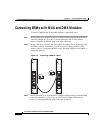
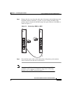
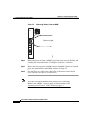
Step 3 Set the remote loopback of the corresponding WCM of the remote system.
The orange loop LED of the WCM in the remote system should be on. The remote
receiver, the remote transmitter, and the local transmitter should operate and
loopback the received signal to the local system. The R/R, R/T, and L/T LEDs
Table 5-1 Tests and Equipment Required
Tests Equipment Required
Optical link loss 1550 nm
specified in dBm referenced to
1mW
• Laser source at 1310 nm and 1550 nm
• A power meter or OTDR
1
1. OTDR = optical time domain reflectometer
Distance specified in km OTDR
Optical return loss 1550 nm
specified in dB
Reflectometer
or
OTDR with a reflectometer